Microdosing
a microdosing and accuracy technology, applied in the field of microdosing, can solve the problems of inability to accurately and consistently control the dose of traditional dosage systems, damage to delicate biotech products, and inability to achieve accurate and consistent doses, and achieve reliable in-process control. the effect of low volum
- Summary
- Abstract
- Description
- Claims
- Application Information
AI Technical Summary
Benefits of technology
Problems solved by technology
Method used
Image
Examples
first embodiment
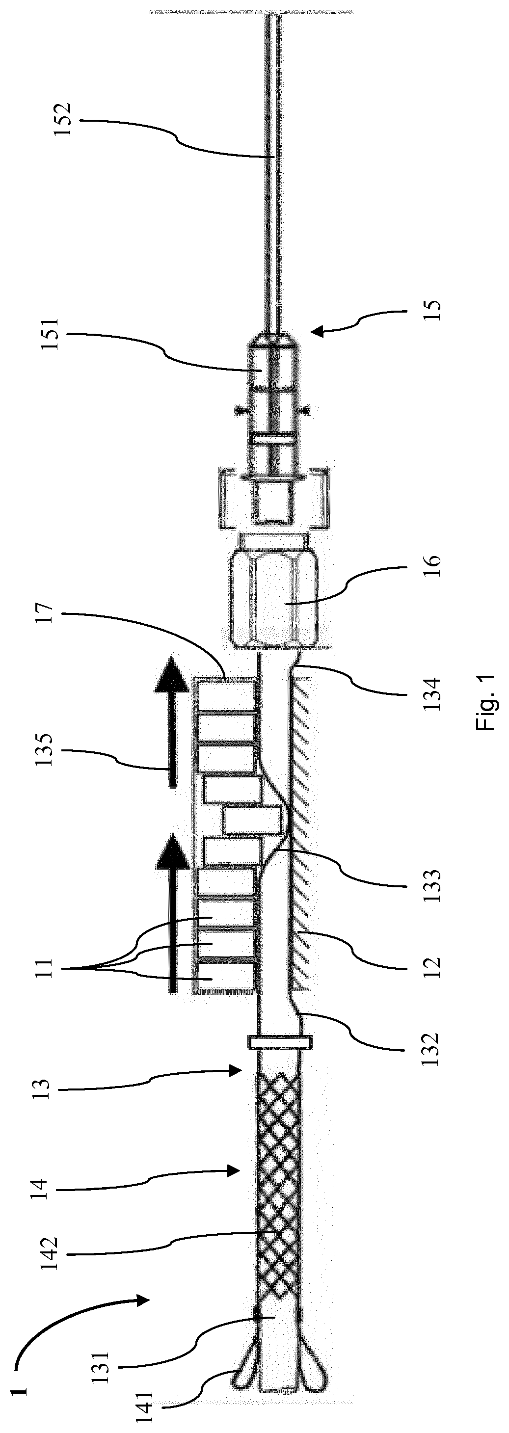
[0130]FIG. 1 shows a linear peristaltic pump 1 of a dosing system according to the invention. In addition to the peristaltic pump 1, the dosing system comprises a control unit 26 and a capacitive pressure sensor 27 as described below in connection with FIG. 7. The peristaltic pump 1 comprises a flexible tube 13, a tube extension jacket 14 as tube fixation structure, a counter pressure plate 12 as counter pressure element, a set of ten parallel piezoelectric actors 11, a dispensing needle 15 as filling needle and a piezoelectric drive unit 17 housing the actors 11 as drive. The tube extension jacket 14 has two straps 141 and a tubular net portion 142. A fixation section 131 of the flexible tube 13 projects through the net portion 142 of the tube extension jacket 14. On expanding the net portion 142, e.g. by pulling the straps 141, it narrows its interior and fixes the flexible tube 13.
[0131]Following the tube extension jacket 14 to the right the flexible tube 13 passes on in between ...
second embodiment
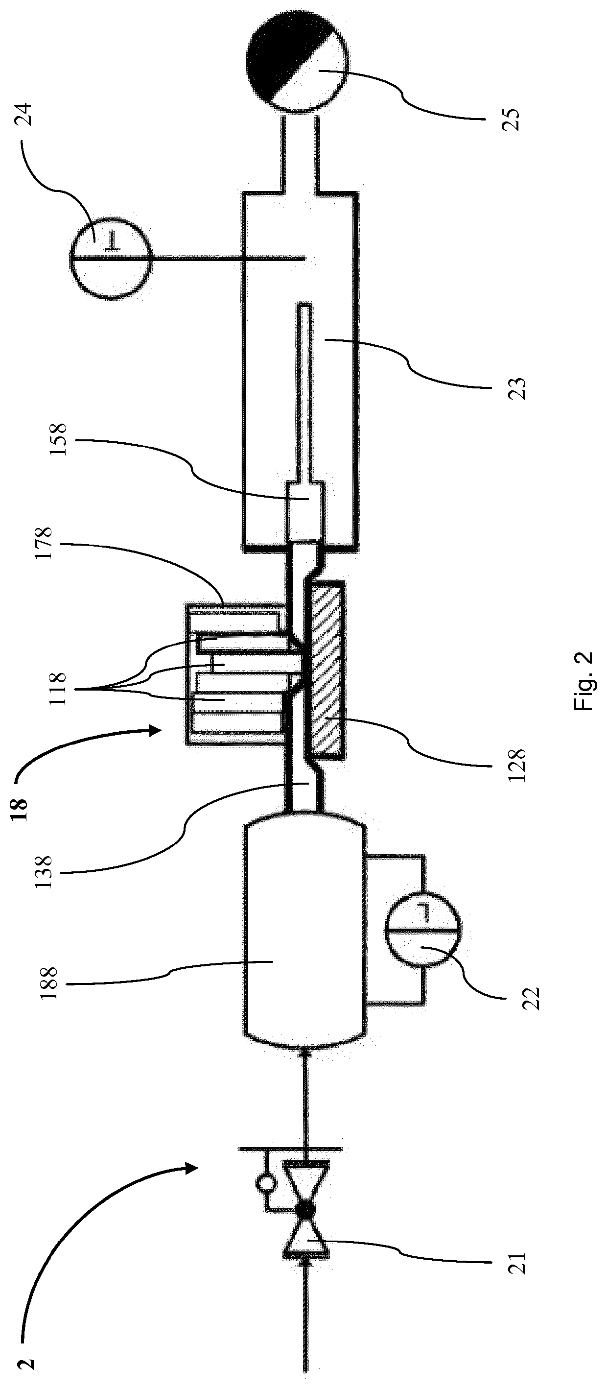
[0140]In FIG. 2 an embodiment of a dosing system 2 according to the invention having a peristaltic pump 18 is shown. In addition to the peristaltic pump 18, the dosing system 2 comprises a control unit 26 and a capacitive pressure sensor 27 as described below in connection with FIG. 7. The peristaltic pump 18 is similarly embodied as the peristaltic pump 1 shown in FIG. 1. It has a dispensing needle 158, a flexible tube 138, a counter pressure plate 128 as counter pressure element and a piezoelectric drive unit 178 housing six parallel piezoelectric actors 118 as drive. The peristaltic pump 18 further comprises a tank 188 as fluid reservoir being connected to a right hand or upstream end of the flexible tube 138.
[0141]The dosing system 2 further comprises a pressure regulator 21 being connected to the tank 188. By means of the pressure regulator 21 a pressure of the fluid inside the tank 188 can be adjusted. The tank 188 is connected to a level sensor 22 sensing a filling level of t...
third embodiment
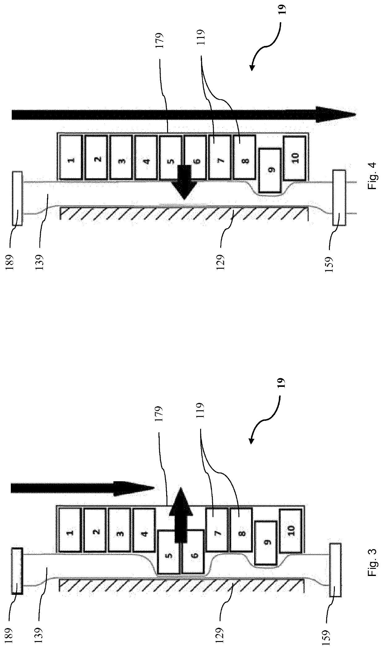
[0144]FIG. 3 shows a peristaltic pump 19 of a dosing system according to the invention being operated in an embodiment of a process according to the invention. The peristaltic pump 19 is similarly embodied as the peristaltic pump 1 shown in FIG. 1 and the peristaltic pump 18 shown in FIG. 2. In a downstream or top-down direction the peristaltic pump 19 comprises a fluid reservoir 189 being connected to a top longitudinal end of a flexible tube 139. The reservoir 189 holds a fluid to dose at an elevated pressure. The flexible tube 139 extends between a counter pressure plate 129 and a ten parallel actors 119, wherein the flexible tube 139 is pre-compressed between the counter pressure plate 129 and the actors 119. The ten actors are housed in a piezoelectric drive unit 179. At its bottom or downstream longitudinal end the flexible tube 139 is connected to a dispensing needle 159. The ten actors 119 are numbered in FIG. 1 from top or upstream first actor 119 to bottom or downstream te...
PUM
 Abstract
Description
Claims
Application Information
 - R&D
- Intellectual Property
- Life Sciences
- Materials
- Tech Scout
- Unparalleled Data Quality
- Higher Quality Content
- 60% Fewer Hallucinations
Browse by: Latest US Patents, China's latest patents, Technical Efficacy Thesaurus, Application Domain, Technology Topic, Popular Technical Reports.
© 2025 PatSnap. All rights reserved.Legal|Privacy policy|Modern Slavery Act Transparency Statement|Sitemap|About US| Contact US: help@patsnap.com


