Apparatus for and method of manufacturing an article using photolithography and a photoresist

Inactive Publication Date: 2021-10-28
BUBENDORFER ANDREA JOCELYN +2
View PDF0 Cites 0 Cited by
  • Summary
  • Abstract
  • Description
  • Claims
  • Application Information

AI Technical Summary

Benefits of technology

The patent describes a method for creating curved structures, such as lenses, by using photoresist and heat to form the desired shape. The process involves exposing the area around the lens and heating it to cure the cross-linked material while the photoresist reflows and melts. The resulting lens structures are optically transparent and can be formed without exposure to UV or hardening with heat alone. The technical effect of this method is the ability to create precision curved structures with improved optical clarity.

Problems solved by technology

Nonetheless, whether conventional or dry film photoresists are used, there can be considerable difficulty, precision, time and expense in producing structures using the above described process, and production of free-standing parts has typically been difficult to achieve.
There can be a limitation in the ability to print structures without patterning previously patterned layers underneath.
This creates a limitation of the Z or depth resolution of about 125 μm with current printing technologies.
However, a further problem is that to align the exposed layer requires mechanical alignment which is difficult to do accurately.

Method used


Image

  • Apparatus for and method of manufacturing an article using photolithography and a photoresist
  • Apparatus for and method of manufacturing an article using photolithography and a photoresist
  • Apparatus for and method of manufacturing an article using photolithography and a photoresist

Examples


example 1

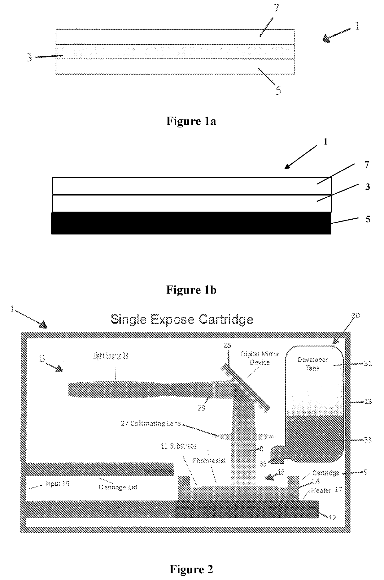
[0198]In one example we provide a dry film pre-laminated photoresist made up of two layers of photoresist material 3, 7, nominally each approximately 5 μm thick. In this example, the top layer 7 is more sensitive to radiation in the form of UV light than the bottom layer 5. This creates a photoresist that can selectively allow or not allow exposure to the laminated layer beneath it.

[0199]Such a photoresist can be used to manufacture a 3D printed article with an overhang. Where there is an overhang, the top layer 7 can be exposed to a lower intensity light (or light of a different wavelength) that does not activate the bottom layer 3. Where there is no overhang a higher intensity light (or light of a different wavelength) can be used to expose through both layers.

[0200]Thus, the two layers of photoresist material have different sensitivities to a characteristic of the radiation from the exposure source. Consequently, in this example, a single exposure source, or at least a single typ...

example 2

[0209]In this example, loading of metal or ceramic particles, or dye, in a layer of photoresist could also prevent or at least control exposure of layers laminated beneath it. The loading of particles can be any desired proportion of the photoresist material, for example the particles might comprise 0.1-50% of the photoresist material.

[0210]The layer of metal / ceramic or dye loaded photoresist will also have the same advantages as described above, in providing a layer of photoresist material having a different sensitivity to radiation than adjacent or other layers of a multi-layer photoresist sheet. Such a variation in sensitivity enables the layers to activate differently when exposed to a common or single source of radiation, or to activated differently when exposed to multiple sources of radiation configured to emit radiation having different characteristics.

[0211]Consequently, this enables the multi-layer photoresist to be laminated first and then exposed —rather than expose (wit...

example 3

[0216]A two layer photo resist was created by laminating a sheet of DF 3510 dry film photoresist onto a substrate and then a sheet of photoresist DF 2020 was laminated on top of this. This created a two layer photoresist material with each layer having different exposure sensitivity characteristics.

[0217]Lines were patterned using a MicroTech LW405A laser writer in one direction on this multilayer photoresist using a 100 mW 406 nm laser and then a further set of lines were patterned at 90 degrees to these lines using a 18 mW 378 nm laser.

[0218]After exposure the multilayer photoresist was cured at 100° C. for 10 minutes to cross-link the structure.

[0219]Following curing, the structures were developed in cyclohexanone to remove all uncross-linked material.

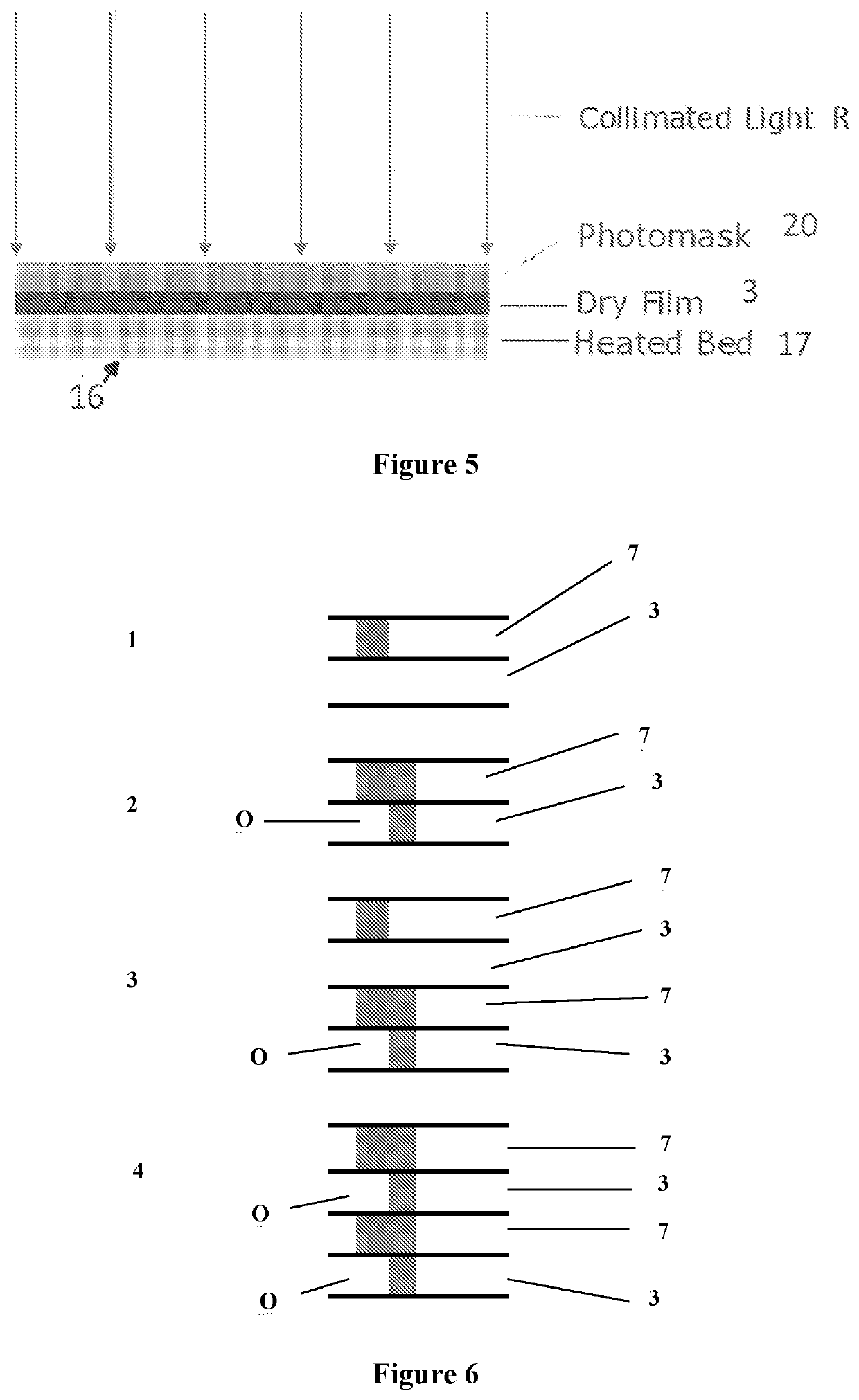
[0220]The resulting images shown in FIG. 6 shows a view from the top with a clear over hang in the top left of the image. The view from the bottom of FIG. 7 shows the pattern of two sets of intersecting lines where one set of lines ...


PUM


Abstract

An apparatus is provided configured to manufacture an article using a multi-layer / laminated photoresist comprising a plurality of layers of photoresist material, where at least a first layer of photoresist material has a first sensitivity to radiation, and at least a second layer of photoresist material has a different sensitivity to radiation. The apparatus comprises: a. a housing configured to receive the photoresist and locate the photoresist in at least one operational position in the housing; b. an exposure system configured to emit radiation which is incident on the photoresist when in the operational position; wherein: i. the exposure system is configured to emit radiation having a first radiation characteristic to induce a change in one or more properties of the area(s) of the first layer of photoresist material exposed to the radiation; and wherein ii. the first radiation characteristic is configured not to induce a change, or to induce a different change, in one or more properties of at least a different one of the layers of photoresist material. Consequently complex articles can be manufactured including hidden or partially visible features, such as overhangs for example.

Description

BACKGROUND OF THE DISCLOSUREField of the Disclosure[0001]The present disclosure generally relates to an apparatus for and method of manufacturing an article using photolithography and a photoresist. In some examples the apparatus and method use a dry film photoresist. An example photoresist is as described in patent application US2006 / 0257785, the entire contents of which are incorporated herein by reference. This disclosure stems from some further work in developing the apparatus and method disclosed in our earlier patent application PCT / NZ2018 / 050030, the entire contents of which are hereby incorporated by reference.Description of the Related Art[0002]In one prior art example, a liquid solution of photoresist material is spun onto a wafer or substrate and then prebaked. The photoresist is then exposed to light in the pattern desired. This causes a chemical change in the photoresist which allows the photoresist to be removed via a developer which is typically a liquid such as sodiu...

Claims


Application Information

Patent Timeline
IPC IPC(8): G03F7/09G03F7/20G03F7/095G03F7/004
CPCG03F7/094G03F7/70008G03F7/0047G03F7/095G03F7/70808G03F7/70025B81C1/00H01L21/67115G03F7/70H01L21/6715G03F7/2051G03F7/2008G03F7/2004G03F7/201G03F7/2037G03F7/091G03F7/0037G03F7/2053B33Y10/00B81C99/0025
Inventor BUBENDORFER, ANDREA JOCELYNBEST, ANDREW DAVID
Owner BUBENDORFER ANDREA JOCELYN
Why Eureka
Try Eureka