Reservoir element and neuromorphic element
- Summary
- Abstract
- Description
- Claims
- Application Information
AI Technical Summary
Benefits of technology
Problems solved by technology
Method used
Image
Examples
first embodiment
(Neuromorphic Element)
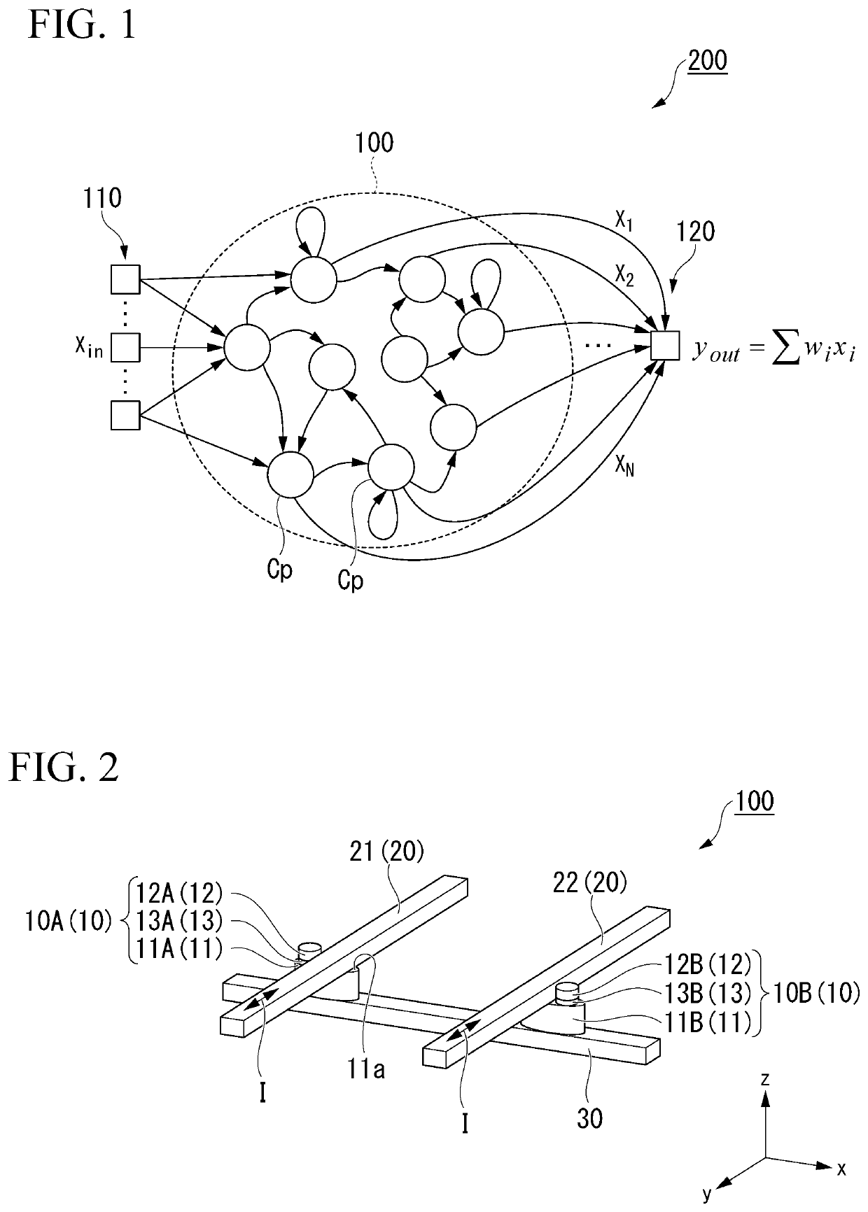
[0038]FIG. 1 is a conceptual view of a neuromorphic element according to a first embodiment. A neuromorphic element 200 has an input part 110, a reservoir element 100 and an output part 120. The input part 110 and the output part 120 are connected to the reservoir element 100.
[0039]The neuromorphic element 200 compresses the signal input from the input part 110 using the reservoir element 100, performs weighting (learning) in the output part 120 on the signal compressed, and outputs the signal to the outside.
[0040]The input part 110 transmits the signal input from the outside to the reservoir element 100. The input part 110 includes, for example, a plurality of sensors. The plurality of sensors detect information outside the neuromorphic element 200, and input the information to the reservoir element 100 as a signal. The signal may be continuously input to the reservoir element 100 over time according to a change in information in the outside, or may be divided...
second embodiment
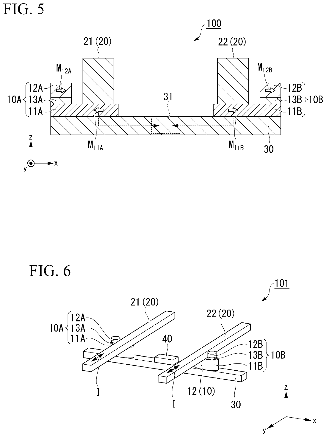
[0098]FIG. 6 is a perspective view of a reservoir element 101 according to a second embodiment. The reservoir element 101 is distinguished from the reservoir element 100 shown in FIG. 2 in that a gate electrode 40 is provided. The other configurations are the same as in the first embodiment and designated by the same reference signs. Description of the same configurations will be omitted.
[0099]The gate electrode 40 faces the spin-conductive layer 30. The gate electrode 40 is disposed between the first magnetoresistive effect element 10A and the second magnetoresistive effect element 10B when seen in plan view from the z-direction.
[0100]The gate electrode 40 includes a known electrode material. When the spin-conductive layer 30 is formed of a metal or an alloy, an insulating layer is preferably provided between the gate electrode 40 and the spin-conductive layer 30.
[0101]The gate electrode 40 applies a voltage to the spin-conductive layer 30. When the voltage is applied to the gate e...
third embodiment
[0103]FIG. 7 is a perspective view of a reservoir element 102 according to a third embodiment. The reservoir element 102 is distinguished from the reservoir element 101 according to the second embodiment in that the number of magnetoresistive effect elements 10 and the number of spin orbit torque wirings 20 are different from those in the second embodiment. The other configurations are the same as in the second embodiment and designated by the same reference signs. Description of the same configurations will be omitted.
[0104]The reservoir element 102 has the plurality of magnetoresistive effect elements 10, the plurality of spin orbit torque wirings 20, the spin-conductive layer 30, and the plurality of gate electrodes 40.
[0105]The plurality of magnetoresistive effect elements 10 are, for example, a first magnetoresistive effect element 10A, a second magnetoresistive effect element 10B, and a third magnetoresistive effect element 10C. The first magnetoresistive effect element 10A, t...
PUM
 Abstract
Description
Claims
Application Information
 - R&D
- Intellectual Property
- Life Sciences
- Materials
- Tech Scout
- Unparalleled Data Quality
- Higher Quality Content
- 60% Fewer Hallucinations
Browse by: Latest US Patents, China's latest patents, Technical Efficacy Thesaurus, Application Domain, Technology Topic, Popular Technical Reports.
© 2025 PatSnap. All rights reserved.Legal|Privacy policy|Modern Slavery Act Transparency Statement|Sitemap|About US| Contact US: help@patsnap.com


