Gearshift mechanism roller

a gearshift mechanism and roller technology, applied in mechanical equipment, transportation and packaging, hoisting equipment, etc., can solve the problems of low stiffness and production-induced tolerances resulting from shrinkage processes, disadvantages, and save bearing generation costs, and achieve good self-cleaning ability and high lateral stiffness

Active Publication Date: 2021-09-23
SRAM
View PDF3 Cites 0 Cited by
  • Summary
  • Abstract
  • Description
  • Claims
  • Application Information

AI Technical Summary

Benefits of technology

[0016]Advantages of such gearshift mechanism rollers composed of metal are: (1) high lateral stiffness; (2) precision; (3) good self-cleaning capability with support structure of open design; (4) technical and visual design freedom.

Problems solved by technology

Normally, the ball bearing is overmoulded already during this primary forming of the chain roller and is thus moulded into the chain roller, which saves costs for the generation of a bearing fit and for the installation of the bearing.
Disadvantages in the case of chain rollers of this type of construction are the low stiffness and the production-induced tolerances resulting from shrinkage processes.
These disadvantages come to bear in particular in the case of chain rollers of large diameter.
A further disadvantage of conventional chain rollers composed of plastics results from the substantially massive and often jagged support structure, which however has scarcely any cutouts, between the bearing region and the toothed region of the chain roller.
It has been found that, in adverse weather conditions, sediment and contaminants accumulate in the region of such support structures of conventional chain rollers.
This results in increased wear, a reduction in drive efficiency owing to friction, and the risk of complete blockage of the gearshift roller owing to foreign bodies becoming jammed between gearshift mechanism roller and chain cage.
In summary, plastics gearshift rollers produced by injection moulding result in the following disadvantages: (1) Low lateral stiffness; (2) Low precision with regard to pitch circle diameter and lateral runout; (3) Poor self-cleaning function in the case of intense contamination.
A disadvantage of chain rollers of this type of construction are the high costs, the manufacturing-induced limitations in the implementation of complex tooth shapes, and the increased noise generation in relation to plastics chain rollers owing to interaction with the chain during riding operation.
A particularly severe disadvantage arises in the case of chain rollers with the actually desired large material cutouts in the spoked support structure.
It has however been found that, with the size of the cutout, the likelihood of relatively large foreign bodies of corresponding length and thickness (in particular relatively small branches) entering the cutouts and blocking the chain roller also increases.
If pedaling is not immediately stopped in such a situation, this can result in a breakaway of the gearshift mechanism, with further consequential damage to the drivetrain and frame.
In summary, the primary disadvantages of milled gearshift mechanism rollers composed of metal are: (1) high costs; (2) restricted design possibilities, in particular in the case of complex tooth geometrie; (3) noise generation; (4) risk of blockage by foreign bodies.
The disadvantages of this integral form, in particular in the case of chain rollers of relatively large diameter, have been discussed further above in the description of the prior art.
These include low lateral stiffness and precision of concentricity, and non-optimal self-cleaning owing to relatively small and at the same time deep and often jagged cutouts 12A, for material and manufacturing reasons, in the region of the support structure 6A.
Additionally, the illustrations are merely representational and may not be drawn to scale.

Method used


Image

  • Gearshift mechanism roller
  • Gearshift mechanism roller
  • Gearshift mechanism roller

Examples


Embodiment Construction

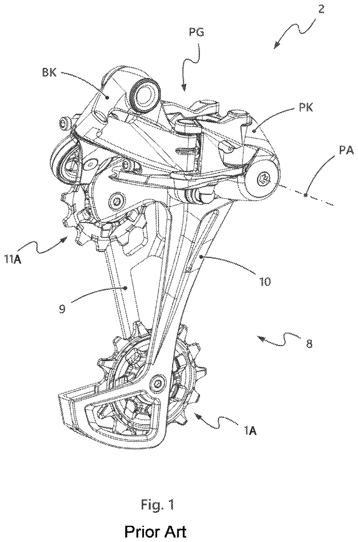
[0027]Proceeding from the background described above, it is therefore the object of the present disclosure to provide a chain roller for a bicycle gearshift mechanism, with which the abovementioned disadvantages are overcome. Here, it is the intention to maintain the advantages of both gearshift mechanism rollers composed of plastic and of those composed of metal.

[0028]The object is achieved by a chain roller having the features of Patent claim 1. The subclaims relate to preferred embodiments.

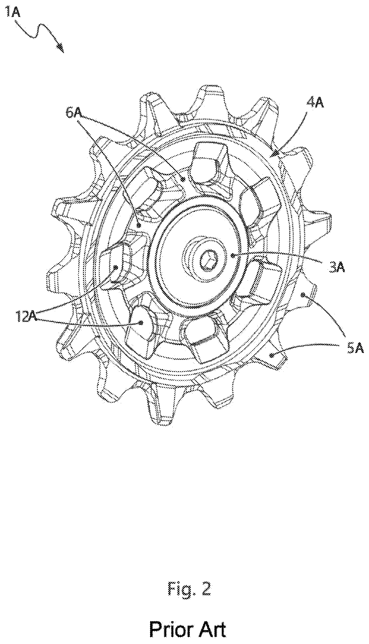
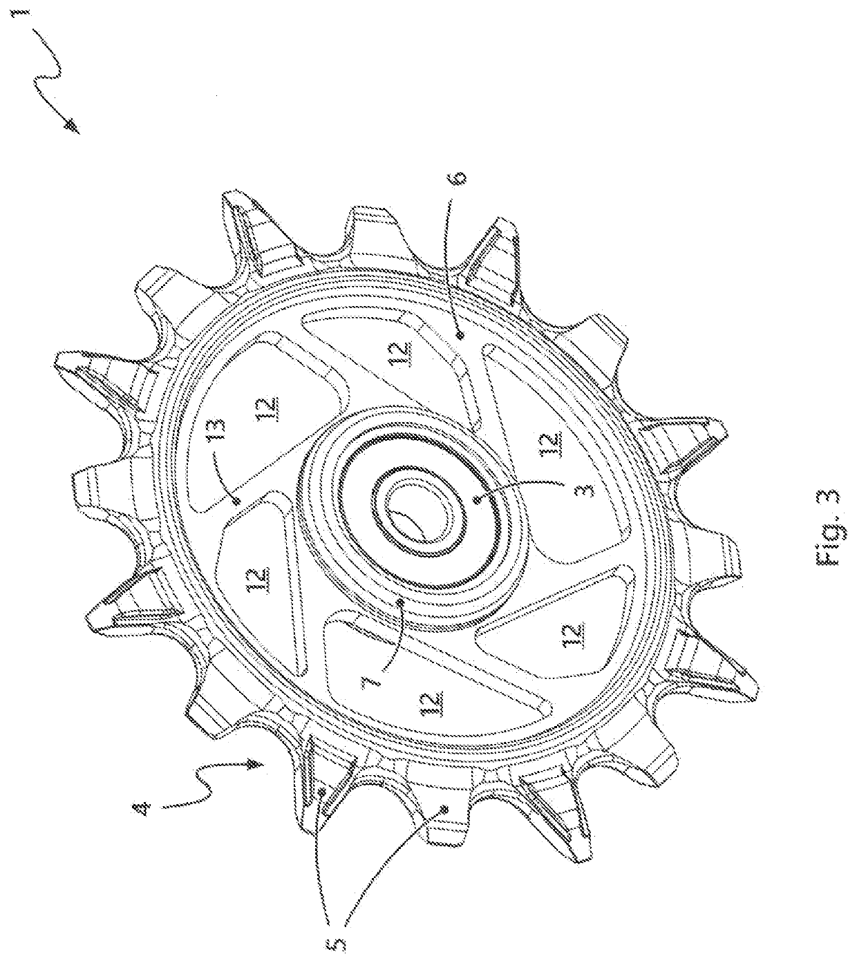
[0029]The chain roller has, in the generic manner, firstly a rotary bearing, a toothed ring with teeth formed thereon, and a support structure which connects the outer ring of the rotary bearing and the toothed ring to one another. The support structure will hereafter also be referred to figuratively as “skeleton”. Depending on the field of use and price category, either ball bearings or plain bearings may be used for the rotary bearing.

[0030]The chain roller is distinguished by the fact that t...


PUM


Abstract

The disclosure relates to a chain roller for a rear bicycle gearshift mechanism. The chain roller comprising a rotatory bearing, a toothed ring with teeth formed thereon, and a support structure which connects the rotary bearing and the toothed ring. The toothed ring and support structure are formed from different materials and are connected to one another radially and axially.

Description

PRIORITY[0001]This application priority to, and / or the benefit of, German Patent Application DE 10 2020 001 877.7, filed on Mar. 23, 2020, the contents of which are hereby incorporated by reference in its entirety.BACKGROUND[0002]Generic chain rollers, hereinafter also referred to as gearshift mechanism rollers, are used in rear bicycle gearshift mechanisms of bicycle derailleurs and, there, are a functional constituent part of the chain cage arrangement, also referred to for simplicity as gearshift mechanism cage or chain cage. The chain cage arrangement of a rear bicycle gearshift mechanism includes an upper chain roller and a lower chain roller, which are commonly arranged between two guide plates of the chain cage.[0003]Generally, the upper chain roller performs the task of guiding the idle strand, which is running onto the pinion assembly, of the chain, in particular for the purposes of exactly controlling the gear change between the various pinions of the pinion assembly. The ...

Claims


Application Information

Patent Timeline
Patent Type & Authority Applications(United States)
IPC IPC(8): B62M9/126F16H55/30
CPCB62M9/126F16H55/30B62M9/00B62M9/121B62M9/16
Inventor BRAEDT, HENRIK
Owner SRAM
Why Eureka
Try Eureka