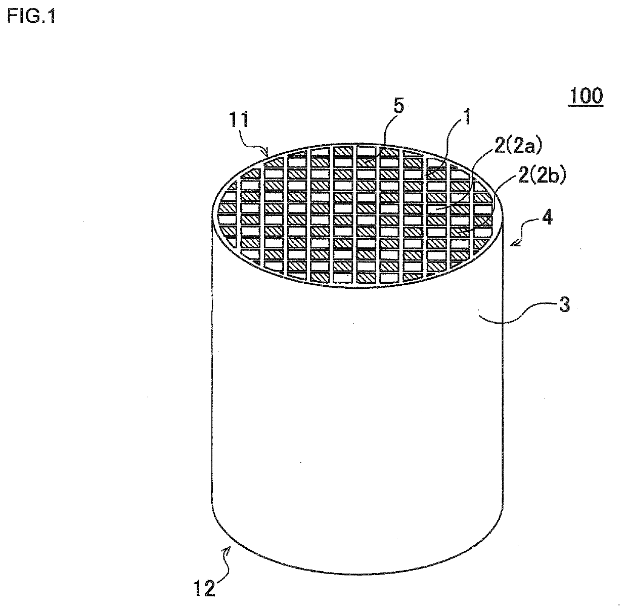
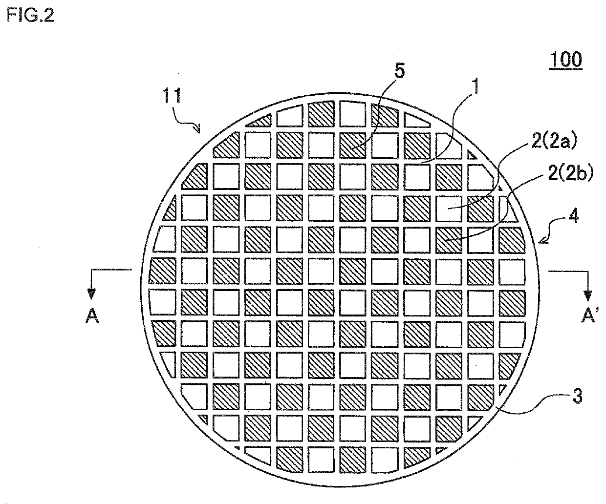
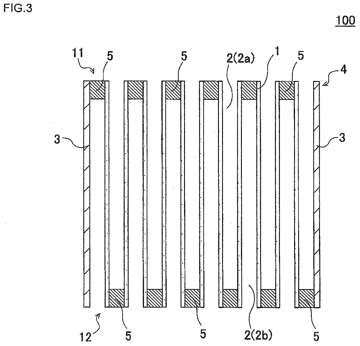
Honeycomb filter

a technology of honeycomb filter and honeycomb filter body, which is applied in the direction of machine/engine, physical/chemical process catalyst, separation process, etc., can solve the problems of inconvenient increase of honeycomb filter pressure loss and lower mechanical strength of honeycomb filter, so as to reduce pressure loss and improve trapping performance. , the effect of high trapping performan

Active Publication Date: 2021-09-02
NGK INSULATORS LTD
View PDF0 Cites 0 Cited by
  • Summary
  • Abstract
  • Description
  • Claims
  • Application Information

AI Technical Summary

Benefits of technology

The present invention provides a honeycomb filter with high trapping performance and reduced pressure loss. This is achieved by setting the average pore diameter of the filter's partition wall to 5 to 10 μm, which improves trapping performance. Additionally, setting the porosity of the partition wall to 55 to 65% reduces pressure loss without compromising mechanical strength. The honeycomb filter also has a sharp first peak in the pore diameter distribution, which helps reduce the ratio of pores with relatively large pore diameters and a small pore volume. This achievement simultaneously improves trapping performance and reduces pressure loss in the honeycomb filter.

Problems solved by technology

However, the average pore diameter of the partition wall significantly influences the pressure loss of the honeycomb filter, and there has been a problem that the pressure loss of the honeycomb filter inconveniently increases when the average pore diameter of the partition wall is reduced.
At this time, the pressure loss could be reduced by further increasing the porosity of the partition wall, but there has been a problem that further increasing the porosity of the partition wall inconveniently leads to lower mechanical strength of the honeycomb filter.

Method used


Image

  • Honeycomb filter
  • Honeycomb filter
  • Honeycomb filter

Examples


example 1

[0056]For the cordierite forming raw material, talc, kaolin, alumina, aluminum hydroxide, and porous silica were prepared. Then, the cumulative particle size distribution of each raw material was measured using a laser diffraction / scattering type particle diameter distribution measurement device (trade name: LA-960) manufactured by HORIBA, Ltd. In Example 1, the raw materials were blended to prepare the cordierite forming raw materials such that the blending ratios (parts by mass) of the raw materials exhibited the values shown in Table 1. In Table 1, the horizontal row of “Particle size D50 (μm)” shows the particle diameter of 50% by volume (i.e., a median diameter) of each raw material.

[0057]Next, 3.0 parts by mass of a water absorbable polymer as an organic pore former, 6.0 parts by mass of a binder, 1 part by mass of a surfactant, and 77 parts by mass of water were added to 100 parts by mass of a cordierite forming raw material to prepare a kneaded material. As the water absorba...

examples 2 to 4

[0082]In Examples 2 to 4, the blending ratios (parts by mass) of the raw materials used for the cordierite forming raw material were changed as shown in Table 1. In addition, the blending ratios (parts by mass) of the organic pore formers and other raw materials were also changed as shown in Table 2. Except that these raw materials were used to prepare the kneaded material, the honeycomb filters were manufactured by the same method as that of Example 1.


PUM

PropertyMeasurementUnit
porosityaaaaaaaaaa
pore diameteraaaaaaaaaa

Abstract

A honeycomb filter includes a pillar-shaped honeycomb structure body having a porous partition wall disposed to surround a plurality of cells and a plugging portion, wherein the partition wall is composed of a material containing cordierite as a main component thereof, porosity of the partition wall measured by a mercury press-in method is 55 to 65%, an average pore diameter of the partition wall measured by a mercury press-in method is 5 to 10 μm, and in a pore diameter distribution indicating a cumulative pore volume of the partition wall measured by a mercury press-in method, with a pore diameter (μm) on an abscissa axis and a log differential pore volume (cm3 / g) on an ordinate axis, a first peak including a maximum value of the log differential pore volume has a pore diameter value of 8 μm or less, the pore diameter value corresponding to a ⅓ value width of the maximum value.

Description

[0001]The present application is an application based on JP 2020-034880 filed on Mar. 2, 2020 with Japan Patent Office, the entire contents of which are incorporated herein by reference.BACKGROUND OF THE INVENTIONField of the Invention[0002]The present invention relates to a honeycomb filter. More specifically, the present invention relates to a honeycomb filter which has high trapping performance and reduces pressure loss.Description of the Related Art[0003]Hitherto, as a filter adapted to trap particulate matter in exhaust gas emitted from an internal combustion engine, such as an automobile engine, or a device adapted to purify toxic gas components, such as CO, HC, and NOx, there has been known a honeycomb filter using a honeycomb structure (refer to Patent Documents 1 and 2). The honeycomb structure has a partition wall formed of porous ceramic, such as cordierite, and includes a plurality of cells defined by the partition wall. In the honeycomb filter, the foregoing honeycomb s...

Claims


Application Information

Patent Timeline
Patent Type & Authority Applications(United States)
IPC IPC(8): F01N3/022B01J35/04B01J35/10
CPCF01N3/0222B01J35/04F01N2330/06B01J35/1076B01J35/108B01D46/2429B01D46/2418F01N2330/48F01N2330/30Y02T10/12B01J35/56B01J35/66B01J35/657
Inventor YOSHIOKA, FUMIHIKOHIRAI, NOZOMUKATO, KYOHEI
Owner NGK INSULATORS LTD
Why Eureka
Try Eureka