
Multiple camera microscope imaging with patterned illumination

a multi-camera, patterned illumination technology, applied in the field of microscope systems, can solve the problems of reducing the resolution of the main objective lens, and limiting the size of the utilized digital detector at the focal plane, so as to improve the resolution improve the final image reconstruction, and improve the effect of the final image reconstruction

Active Publication Date: 2021-08-19
RAMONA OPTICS INC
View PDF0 Cites 0 Cited by
  • Summary
  • Abstract
  • Description
  • Claims
  • Application Information

AI Technical Summary

Benefits of technology

The MCPI imaging system can capture high-resolution images of samples using a miniature camera array. The system can have a resolution of 3-15 μm in a single snapshot, with the FOV (field of view) of each micro-camera overlapping with one or more others. The system can also use patterned illumination and post-processing to improve the resolution and measure the height profile, optical phase, and aberrations of samples. Additionally, the system has a compact size, does not require a moving parts, and can operate in small spaces.

Problems solved by technology

To image across a larger FOV, one is typically forced to design a microscope objective lens that offers a poorer resolution.
Due to this tradeoff, most standard microscopes are only able to capture a maximum of 50 million resolvable spots (i.e., 50 megapixels) per image.
However, this type of approach does not attempt to image a contiguous FOV, but instead just multiple narrow segments of the sample of interest, as with other alternative designs [Ref PTL3-Ref PTL6].
However, the FOV of the arrangement in [Ref NPL8] remains limited to the size of the utilized digital detector at the focal plane, which is still relatively small (no more than 100 mm across, and often less with smaller pixels).
However, such approaches offer a resolution and FOV that is still limited to that defined by the main objective lens.
However, no designs besides the MCPI microscope use multiple micro-cameras to capture light from the same sample area (i.e., capture overlapping FOV's) while at the same time providing patterned illumination.
Furthermore, the prior art is designed for far field macroscopic imaging (of objects multiple meters to kilometers away), is not amenable to a configuration for microscope imaging, requires highly coherent resolution (e.g. from a laser and not from LEDs), and also does not attempt 3D image reconstruction.
However, this work also considers the case of a highly coherent source that would spread the spectrum evenly across all of the cameras in the array, and this design does not consider cameras with overlapping FOVs.
It does not attempt to image a contiguous FOV, and is thus not applicable to generally unaligned samples.
However, to the best of our knowledge, this prior work has only been demonstrated in optical systems that contain a single microscope objective lens and capture a single image FOV.

Method used


Image

  • Multiple camera microscope imaging with patterned illumination
  • Multiple camera microscope imaging with patterned illumination
  • Multiple camera microscope imaging with patterned illumination

Examples


examples

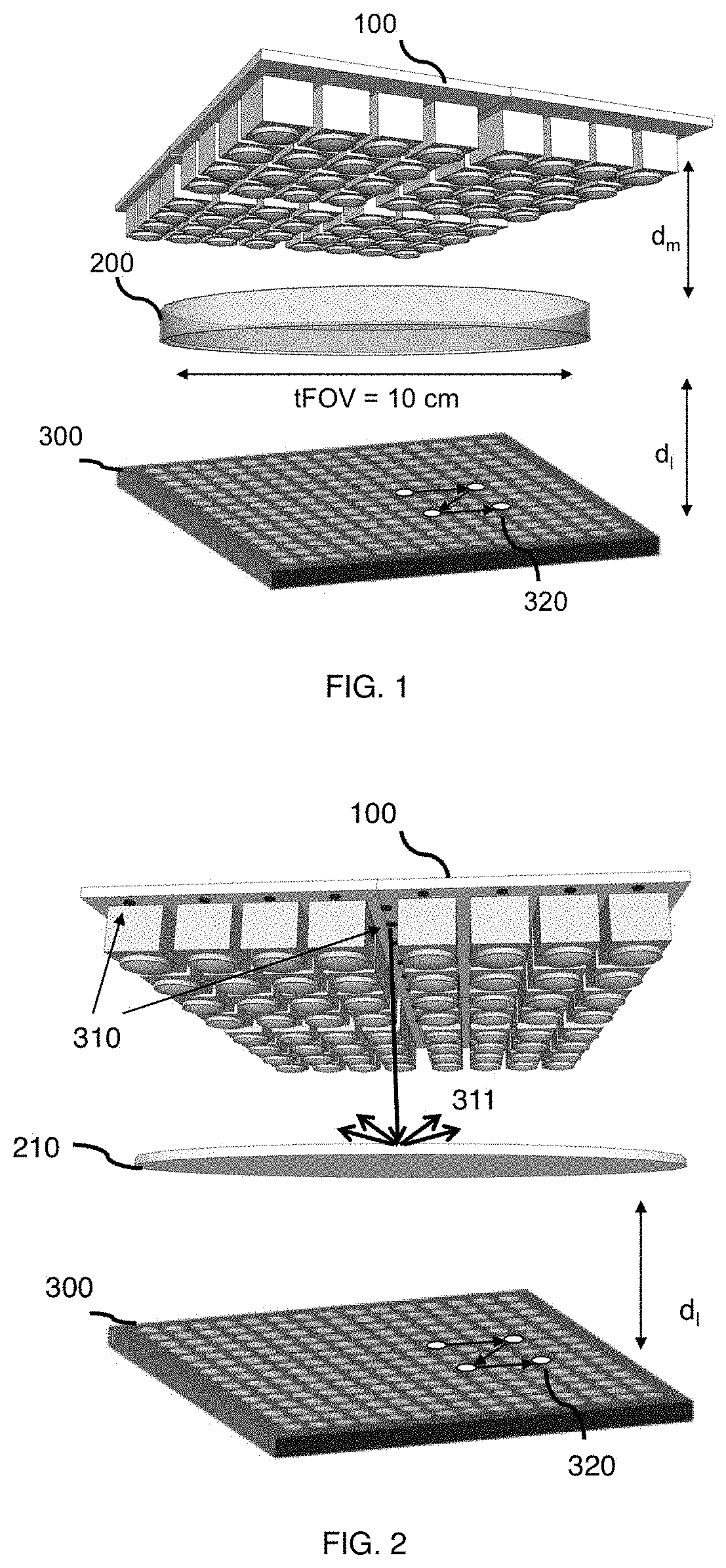
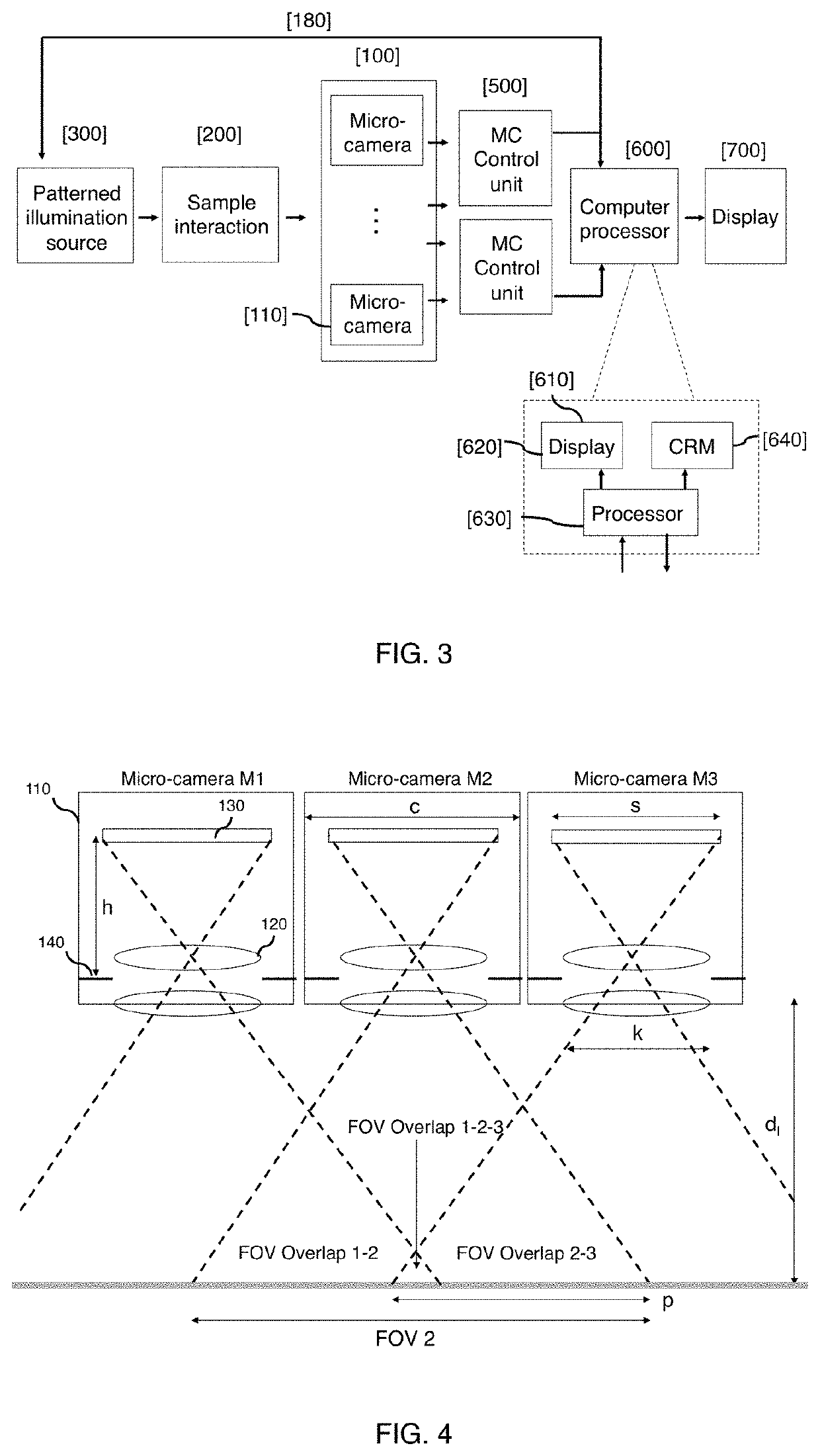
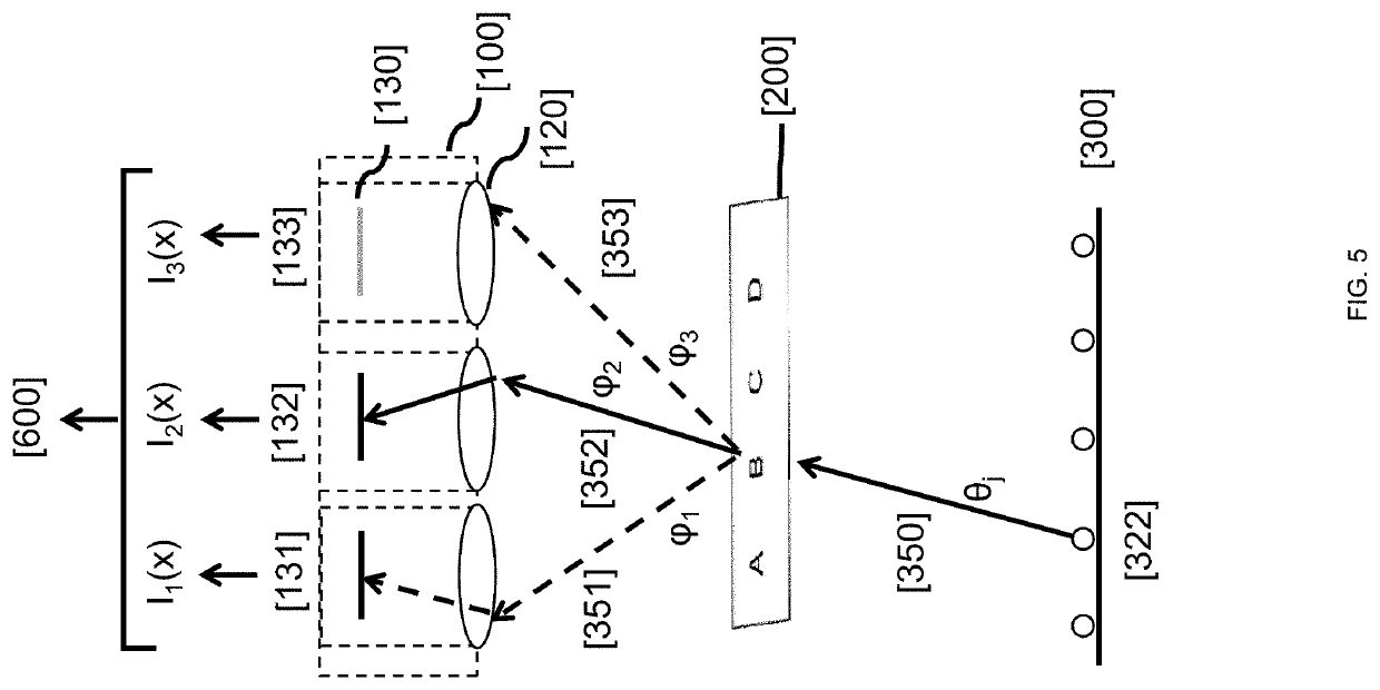
[0037]Light from the patterned illumination source exits the sample from many spatial locations. Some of this light may then propagate to the micro-camera array. Considering one spatial location along the sample, the light exiting this location will pass through one or more micro-camera lenses to form one or more images. In the most general arrangement, each micro-camera can image a distinct sample region to its image plane and will record the intensity of this optical field on a digital detector array (e.g., a CMOS or CCD pixel array). We also note that the micro-cameras do not necessarily have to form an exact image (e.g., can be defocused or otherwise optically modified, e.g., as by a coded aperture). We denote the area of the sample from which light has interacted with, and can then enter into micro-camera number n (here denoted as Mn), as field-of-view n (here denoted as FOVn). What makes the MCPI camera array geometry distinct from other camera arrays used for microscopy is it...


PUM


Abstract

An array of more than one digital micro-camera, along with the use of patterned illumination and a digital post-processing operation, jointly create a multi-camera patterned illumination (MCPI) microscope. Each micro-camera includes its own unique lens system and detector. The field-over-view of each micro-camera unit at least partially overlaps with the field-of-view of one or more other micro-camera units within the array. The entire field-of-view of a sample of interest is imaged by the entire array of micro-cameras in a single snapshot. In addition, the MCPI system uses patterned optical illumination to improve its effective resolution. The MCPI system captures one or more images as the patterned optical illumination changes its distribution across space and / or angle at the sample. Then, the MCPI system digitally combines the acquired image sequence using a unique post-processing algorithm.

Description

[0001]The present patent application is a continuation of U.S. application Ser. No. 16 / 066,065, filed on Jun. 26, 2018, now U.S. Pat. No. 10,976,535, which claims priority from International application PCT / US2017 / 024610 filed on Mar. 28, 2017, which claims priority from U.S. Provisional application 62 / 315,037, filed on Mar. 30, 2016, all of which are herein incorporated by reference in their entirety.TECHNICAL FIELD[0002]This invention relates to a microscope system that reconstructs images using multiple cameras, patterned illumination and computational post-processing.BACKGROUND ART[0003]Current microscopes exhibit a tradeoff between their resolution and field-of-view (FOV). To image across a larger FOV, one is typically forced to design a microscope objective lens that offers a poorer resolution. Due to this tradeoff, most standard microscopes are only able to capture a maximum of 50 million resolvable spots (i.e., 50 megapixels) per image. This invention relates to a microscope...

Claims


Application Information

Patent Timeline
Patent Type & Authority Applications(United States)
IPC IPC(8): G02B21/36G02B21/06H04N5/225H04N5/232H04N5/247
CPCG02B21/367G02B21/06G01N21/6458H04N5/23229H04N5/247H04N5/2256G01B11/2545G06T5/50G06T2207/10056G06T2207/10152G06T7/593H04N23/56H04N23/45G06T5/73H04N23/80H04N23/90
Inventor HORSTMEYER, ROARKEHORSTMEYER, ROBERTHARFOUCHE, MARK
Owner RAMONA OPTICS INC
Learn More