Positive electrode material, non-aqueous electrolyte secondary battery, and method of producing positive electrode material

a technology of non-aqueous electrolyte and secondary batteries, which is applied in the direction of positive electrodes, electrode manufacturing processes, cell components, etc., can solve the problems of reducing cycle life, conductive materials not contributing to battery capacity, and oxidative degradation of electrolyte, so as to improve cycle life, improve cycle life, and reduce battery resistance

Pending Publication Date: 2021-07-29
TOYOTA JIDOSHA KK +1
View PDF3 Cites 0 Cited by
  • Summary
  • Abstract
  • Description
  • Claims
  • Application Information

AI Technical Summary

Benefits of technology

The patent text discusses the use of a boron oxide film on the surface of a positive electrode active material particle to improve the performance of non-aqueous electrolyte secondary batteries. The films help reduce direct contact between the particles and electrolyte, which can improve battery performance and extend the battery's cycle life. In summary, the patent aims to provide a positive electrode material that results in batteries with better energy density, lower battery resistance, and longer cycle life.

Problems solved by technology

Because of this, on surfaces of positive electrode active material particles, oxidative degradation of electrolyte may occur.
Oxidative degradation of electrolyte may be a cause of a decrease in cycle life.
However, conductive material does not contribute to battery capacity.
Increasing the amount of conductive material may cause a decrease in battery energy density.
However, adding conductive material 4 after formation of film 2 on a surface of base material particle 1 may be less likely to achieve forming electronic conduction paths that connect base material particles 1 to each other.
Further, increasing the amount of conductive material 4 may cause a decrease in battery energy density.
Therefore, use of conductive material 4 in an attempt to reduce an increase in resistance resulting from film formation may be inefficient.
As a result, an increase in resistance resulting from film formation may be reduced efficiently.

Method used


Image

  • Positive electrode material, non-aqueous electrolyte secondary battery, and method of producing positive electrode material
  • Positive electrode material, non-aqueous electrolyte secondary battery, and method of producing positive electrode material
  • Positive electrode material, non-aqueous electrolyte secondary battery, and method of producing positive electrode material

Examples


example 1

[0107]

[0108]>

[0109]Materials described below were prepared.

[0110]Base material particle: Positive electrode active material (LiNi0.8Co0.1Mn0.1O2)

[0111]Boric acid: H3BO3

[0112]CNT: SWCNT (with a diameter from 2 nm to 4 nm and a length from 10 μm to 30 μm)

[0113]Solvent: Water

[0114]The base material particles, the boric acid, the carbon nanotubes, and the solvent were mixed to prepare a first precursor. The amount (amount of substance) of boric acid was 1% of the amount of substance of the positive electrode active material.

[0115]>

[0116]A dryer was used to dry the first precursor. Thus, a second precursor was prepared.

[0117]>

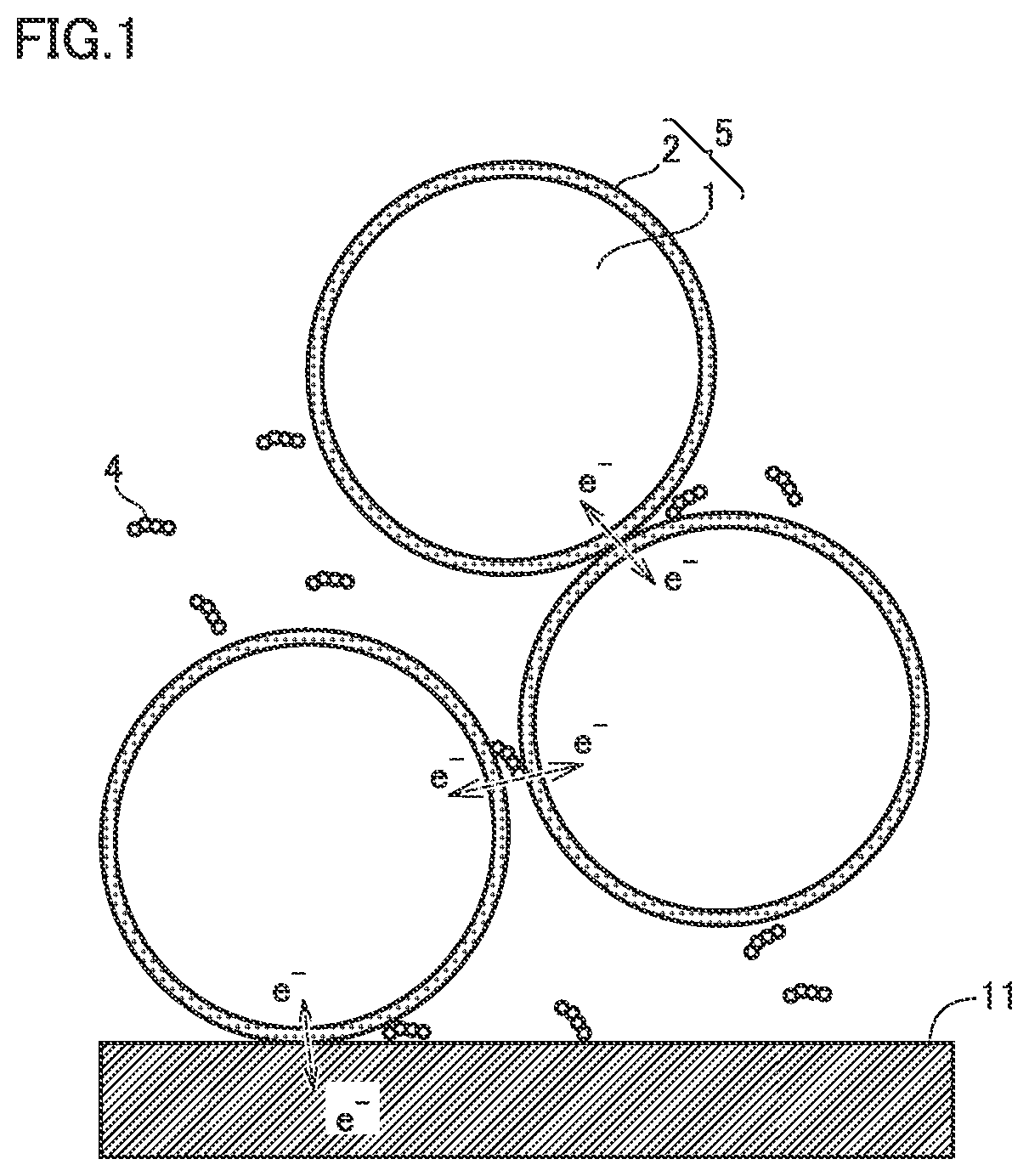
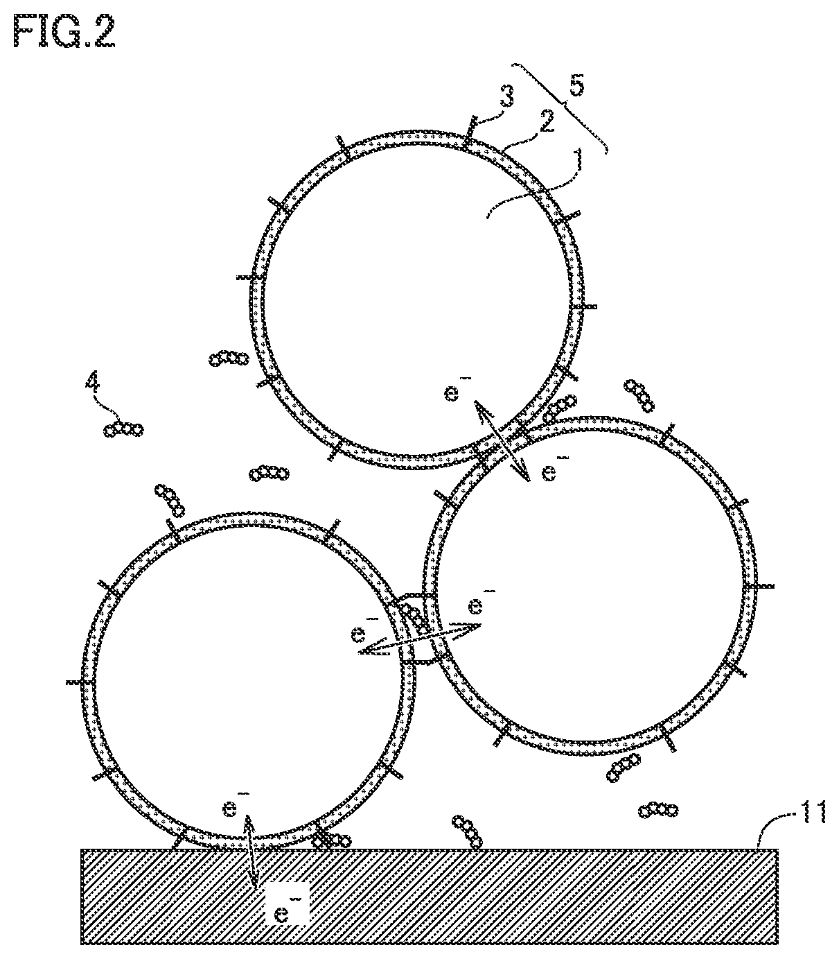
[0118]An electric furnace was used to heat the second precursor. The heating atmosphere was air. The heating temperature was 250° C. Thus, composite particles 5 were formed. Aggregates of composite particles 5 were disaggregated. Thus, a plurality of composite particles 5 were formed. In other words, a positive electrode material was produced. In Example 1, CNTs we...

example 2 to example 7

[0144]A positive electrode material and then a non-aqueous electrolyte secondary battery were produced in the same manner as in Example 1 except that the “boron ratio” and the “CNT ratio” were changed as specified in Table 1 below.


PUM

PropertyMeasurementUnit
median diameteraaaaaaaaaa
electric potentialaaaaaaaaaa

Abstract

A positive electrode material consists of composite particles. Each of the composite particles includes a base material particle, a film, and a carbon nanotube. The film covers at least a part of a surface of the base material particle. The base material particle includes a positive electrode active material. The film includes a boron oxide. The carbon nanotube includes a first portion and a second portion. The first portion is buried in the film. The second portion is exposed on a surface of the film.

Description

CROSS REFERENCE TO RELATED APPLICATIONS[0001]This nonprovisional application claims priority to Japanese Patent Application No. 2020-009752 filed on Jan. 24, 2020 and No. 2021-006947 filed on Jan. 20, 2021, with the Japan Patent Office, the entire contents of which are hereby incorporated by reference.BACKGROUNDField[0002]The present disclosure relates to a positive electrode material, a non-aqueous electrolyte secondary battery, and a method of producing a positive electrode material.Description of the Background Art[0003]Japanese Patent Laying-Open No. 2014-127235 discloses an amorphous boron oxide coating layer that covers at least a part of a surface of a positive electrode active material particle.SUMMARY[0004]In a non-aqueous electrolyte secondary battery (which may be simply called “battery” hereinafter), positive electrode active material particles have a high electric potential. Because of this, on surfaces of positive electrode active material particles, oxidative degradat...

Claims


Application Information

Patent Timeline
Patent Type & Authority Applications(United States)
IPC IPC(8): H01M4/133H01M4/131H01M4/134H01M4/1391H01M4/1395H01M4/1393H01M4/36C01B32/162H01M4/04
CPCH01M4/133H01M4/131H01M4/134H01M4/1391H01M2004/028H01M4/1393H01M4/364C01B32/162H01M4/0471H01M4/1395Y02E60/10H01M4/366H01M4/625H01M4/62H01M2004/021H01M4/525H01M4/505H01M4/5825
Inventor HANAZAKI, RYOKO, TAKASHIGOTO, NATSUMITSURUTA, SHOKINTSU, KOHEI
Owner TOYOTA JIDOSHA KK
Why Eureka
Try Eureka