Eureka AIR delivers breakthrough ideas for toughest innovation challenges, trusted by R&D personnel around the world.

Method for measuring corrosion-expansion force during cracking of concrete due to corrosion and expansion of reinforcing steel

a technology of reinforcing steel and cracking concrete, which is applied in the field of concrete corrosion, can solve the problems of cracking of the concrete protective layer, inability to monitor a change in the corrosion-expansion force in real time, and corrosion of the reinforcing steel, and achieves low cost and safe and reliable operation.

Active Publication Date: 2021-07-01
QINGDAO TECHNOLOGICAL UNIVERSITY
View PDF0 Cites 5 Cited by
  • Summary
  • Abstract
  • Description
  • Claims
  • Application Information

AI Technical Summary

Benefits of technology

The present invention is a method to monitor the change in corrosion-expansion force of reinforced concrete in real time using two CCD cameras and a computer. The cameras are adjusted to capture the front and upper surfaces of the concrete test block without strain gauges and with a clear image. The method also includes adjusting the light intensity to prevent overexposure or wash-out of the speckle on the surface of the concrete test block. The method is simple, safe, reliable, and low-cost.

Problems solved by technology

However, with an increase in application scenarios of the reinforced concrete materials, the reinforced concrete structure serving in humid environments such as a coastal port is corroded by chloride salts to cause the alkaline environment of the concrete to fail and the passivation film of the reinforcing steel to rupture, resulting in the corrosion of the reinforcing steel.
Eventually, corrosion products of the reinforcing steel cause cracking of the concrete protective layer.
However, these existing methods cannot monitor a change in the corrosion-expansion force in real time, and are more difficult to implement and costly.

Method used


Image

  • Method for measuring corrosion-expansion force during cracking of concrete due to corrosion and expansion of reinforcing steel
  • Method for measuring corrosion-expansion force during cracking of concrete due to corrosion and expansion of reinforcing steel
  • Method for measuring corrosion-expansion force during cracking of concrete due to corrosion and expansion of reinforcing steel

Examples


embodiment

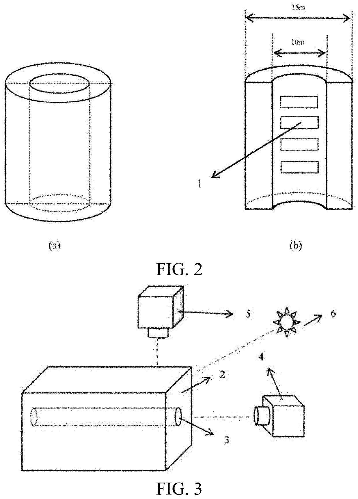
[0030]In this embodiment, reinforcing steel is a hollow steel pipe, an inner diameter of the steel pipe is 10 mm, and an outer diameter is 16 mm. A strain 1 is pasted inside the steel pipe to measure strain in an inner wall of the reinforcing steel, and derive corrosion-expansion force on a surface of the reinforcing steel according to the theory of elastic mechanics, to compare the derived corrosion-expansion force with corrosion-expansion force obtained by using the method described in this example to verify validity of a measurement result. Specific steps are as follows:

[0031](1) First, the steel pipe is longitudinally cut along an axis, and one strain gauge 1 is pasted in an inner ring of the steel pipe according to actual requirements to measure internal strain of the steel pipe.

[0032](2) A square concrete test block 2 with a steel tube 3 embedded in the middle is made, a cross section of the steel tube 3 being flush with a surface of the concrete test block. After curing for t...


PUM


Abstract

A method for measuring corrosion-expansion force during cracking of concrete due to corrosion and expansion of reinforcing steel; wherein, deformation on a surface of reinforced concrete is photographed based on a digital image correlation (DIC) method, a full-field displacement and a full-field strain on a surface of the concrete are analyzed and calculated, a relationship between corrosion-expansion force and the strain on the surface of the concrete is found through an established theoretical model, and corrosion-expansion force of reinforcing steel and a change rule of the corrosion-expansion force are calculated. Therefore, the method is simple and includes with safe and reliable operations, scientific principles, and low costs, so that a change in corrosion-expansion force during corrosion and expansion of reinforced concrete can be monitored in real time.

Description

BACKGROUNDTechnical Field[0001]The present invention belongs to the technical field of concrete corrosion, and relates to a method for measuring corrosion-expansion force during corrosion of reinforcing steel in concrete through non-destructive monitoring, and in particular, to a method for measuring corrosion-expansion force during cracking of concrete due to corrosion and expansion of reinforcing steel. Therefore, a digital image correlation (DIC) method is used to monitor information such as a displacement and a strain of a surface of reinforced concrete in real time, and corrosion-expansion force of reinforcing steel in concrete is derived through an established theoretical model, to analyze a change rule of the corrosion-expansion force of the reinforcing steel during corrosion.Related Art[0002]In the early 19th century, reinforced concrete materials brought a revolution in the construction field, and more and more buildings were built with the reinforced concrete materials. Re...

Claims


Application Information

Patent Timeline
IPC IPC(8): G01N33/38G01N17/00G01L5/1627H04N5/247H04N5/225G06T7/00
CPCG01N33/383G01N17/00G01L5/1627G06T2207/30132H04N5/2256G06T7/001H04N5/247G01L5/00G06T7/248G06T7/0004G06T2207/10016G06T2207/30136G01M5/005G01M5/0033G01M11/081H04N23/90H04N23/56
Inventor CHEN, FANXIUZHANG, BINGUO, PENGFEIJIN, ZUQUAN
Owner QINGDAO TECHNOLOGICAL UNIVERSITY
Why Eureka
Eureka Blog
Learn More