Method for the continuous production of optical fibre waveguides mounted in a thin-walled, radially closed metal tube

a technology of optical fibre and metal tube, which is applied in the direction of manufacturing tools, instruments, other domestic objects, etc., can solve the problems of reducing the quality of optical fibre, and increasing the length of earth cable and metal tube, so as to reduce the wall thickness, the effect of saving valuable resources and high quality

Pending Publication Date: 2021-05-27
NEXANS
View PDF10 Cites 3 Cited by
  • Summary
  • Abstract
  • Description
  • Claims
  • Application Information

AI Technical Summary

Benefits of technology

This patent describes a process for creating hollow profiles made from metal strips. The process involves shaping the metal strip into a desired shape through bending, which can occur in stages. The finished product has a thinner wall thickness, which can make it easier to transport and install. The upright oval shape of the hollow profile also offers advantages during closure. Overall, the process allows for the creation of thin, lightweight hollow profiles with excellent strength and durability.

Problems solved by technology

This constitutes a problem in particular in the presence of high temperatures, because the earth cable and the metal tube become longer, and sag, when warmed.
The glass fibre expands to a much lesser extent and is subjected to intense tensile stress, which ultimately leads to breakage of the fibre and thus to an interruption of the communication path led via said fibre.
Only at this point in time is the fibre subjected to a tensile stress which exceeds the tensile stress caused by the fibre's own weight and which can ultimately lead to breakage of the fibre.
Such embodiments are however generally not economical and not practicable owing to the large required dimensions of the metal tube.
During the production process, the uniform distribution of the excess length of the fibre in the tube is difficult to set and monitor.
Wall thicknesses smaller than 0.15 mm however cannot be welded reliably by means of such methods.
The tubes welded using the known arc method furthermore exhibit a pronounced weld bead, which projects into the tube interior and exposes fibre waveguides mounted therein to the risk of mechanical damage.
Furthermore, tubes with a diameter of less than Ø 0 4.0 mm cannot be produced using the known method.
In particular, the uniform distribution of the excess length over the entire length of the manufactured metal tube cannot be checked.
The distribution of the average excess length cannot be determined, and if the control measurement yields that a defect is present, the entire manufactured product cannot be used.
The conventional production methods may furthermore be limited with regard to the line lengths that can be produced in one piece, which is undesirable in the case of a large required length owing to the necessary connections of successive line segments.
Furthermore, the excess length of the fibre is only statistically uniformly distributed; it is in fact not possible with conventional methods to ensure a uniform distribution of the excess length of the fibre, such that a breakage of the fibre cannot be reliably ruled out in the case of an expansion of the metal tube which, statistically on average, is still tolerable.

Method used


Image

  • Method for the continuous production of optical fibre waveguides mounted in a thin-walled, radially closed metal tube
  • Method for the continuous production of optical fibre waveguides mounted in a thin-walled, radially closed metal tube
  • Method for the continuous production of optical fibre waveguides mounted in a thin-walled, radially closed metal tube

Examples


Embodiment Construction

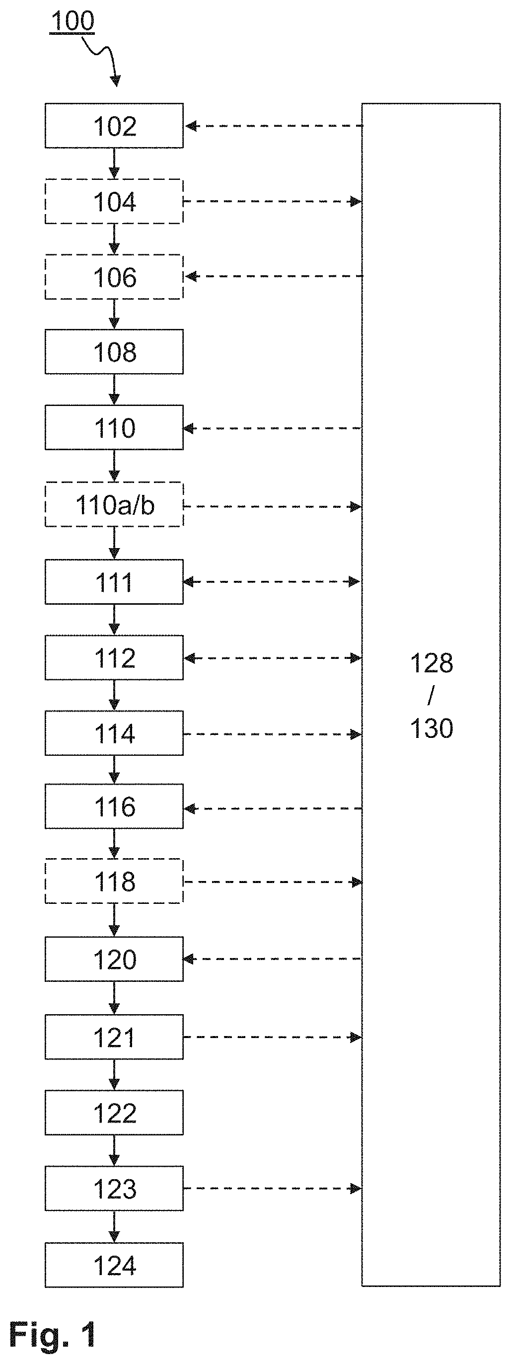
[0060]FIG. 1 shows steps of an exemplary method 100 for producing a thin-walled, radially closed metal hollow profile, with fibre waveguides of excess length mounted therein, according to one aspect of the invention. In step 102 of the method, a flat metal strip is supplied with a first supply speed to a deforming unit, for example is unwound from a coil. In the deforming unit, the supplied flat metal strip is, in step 108, deformed to form a shape corresponding to the desired hollow profile. The deformation may be performed for example by means of a roll forming tool.

[0061]Prior to the deformation, in a cutting unit, an optional step 106 may be performed in which one or both edges of the metal strip are trimmed or prepared in some other way. In this way, even in the case of poor edge quality of the metal strip, the width of the strip can be uniformly and precisely set, and the edges can if necessary be prepared for a subsequent welding process. The cutting unit may be supplied with...


PUM

PropertyMeasurementUnit
Temperatureaaaaaaaaaa
Lengthaaaaaaaaaa
Forceaaaaaaaaaa

Abstract

For the production of fibre waveguides mounted in a metal hollow profile, a flat metal strip is supplied to a deforming unit. The deforming unit is configured for continuously deforming the supplied flat metal strip into a shape corresponding to the hollow profile. The hollow profile is continuously welded along a longitudinal seam by means of a laser. A filler gel with a viscosity which increases with decreasing temperature, and one or more fibre waveguides, are introduced into the welded hollow profile in a continuous process via a guide or protective tube. In order to introduce the one or more fibre waveguides with an excess length into the hollow profile, the welded hollow profile is elastically stretched, is cooled, and is relaxed again. The finished product is received in a receiving unit. The continuous closed-loop control of the excess length of the fibre waveguides is performed inter alia through continuous open-loop control of the gel temperature, of the laser power and of the force exerted on the hollow profile for the elastic stretching.

Description

RELATED APPLICATION[0001]This application claims the benefit of priority from PCT Patent Application No. PCT / IB209 / 001284, filed on Nov. 15, 2019, the entirety of which is incorporated by reference.FIELD[0002]The invention relates to the production of optical fibre waveguides with an external casing composed of metal, in particular the continuous production of such fibre waveguides with thin-walled casing.BACKGROUND[0003]Fibre waveguides for the optical transmission of signals, also referred to as optical waveguides or light conductors, are, depending on the application and requirements on mechanical stability and protection against environmental influences and hydrogen diffusion, encased with a shell composed of plastic or with a metal shell. Fibres in a metal shell are used for example in the case of undersea cables and are commonly also led as a communication channel in earth wires of high-voltage lines. In the latter application, the metal shell is of major importance as a light...

Claims


Application Information

Patent Timeline
IPC IPC(8): B23K26/262B23K26/00B23K26/03B23K26/035B23K26/08B23K26/20B23K26/32B23K31/00
CPCB23K26/262B23K26/0093B23K26/032B23K26/034B23K2101/06B23K26/083B23K26/206B23K26/32B23K31/003B23K26/035B23K26/21B23K26/702G02B6/10G02B6/4488G02B6/4484B23K2103/50B21C37/0822
Inventor EGERER, RALFPETERSEN, OLAFDINKEL, STEVEN
Owner NEXANS
Why Eureka
Try Eureka