
Core-bobbin assembly and motor cooling method using the same

a cooling method and core bobbin technology, applied in the direction of electric propulsion mounting, vehicle sub-unit features, magnetic circuit shape/form/construction, etc., can solve the problems of motor not operating, motor stops, motor weight is increased, etc., to reduce the weight of the motor, reduce the fuel consumption, and reduce the weight

Pending Publication Date: 2021-04-22
HYUNDAI MOBIS CO LTD
View PDF13 Cites 0 Cited by
  • Summary
  • Abstract
  • Description
  • Claims
  • Application Information

AI Technical Summary

Benefits of technology

The present invention is about an improved structure of a core-bobbin assembly for a motor. This structure eliminates the need for a support ring, O-ring, and gasket that are used to support and cool the assembly, reducing the weight and increasing the heat transfer area. The improvement also allows for better cooling of the entire surface of the outer circumferential portion of the core to prevent damage to terminals or delamination of the core. The result is a decrease in fuel consumption and better motor performance. The improved structure also provides better water tightness and prevents delamination of the core for better insulation. Overall, the invention is about making the motor cooling system more efficient and effective while reducing weight and cost.

Problems solved by technology

When such a heating amount is increased, serious problems are generated.
Burning or dielectric breakdown problems of the coil, a terminal assembly, and the like in which the current flows may be generated, and as a result, the motor does not operate, and thus a vehicle stops.
Therefore, cooling of the motor to which much electric energy is supplied is an important issue.
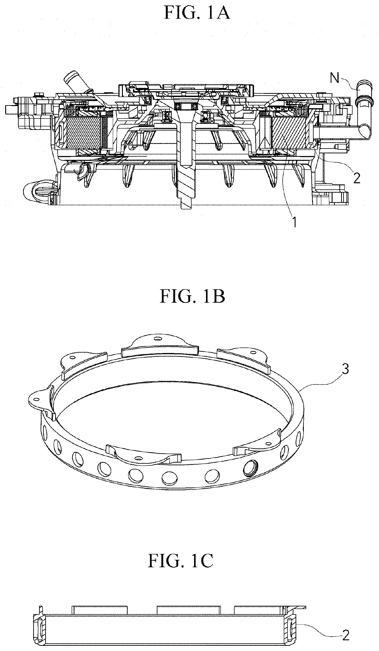
The conventional support rings for cooling a motor for an EV have a disadvantage in that a weight thereof is large.
The second type has advantages in that a weight is light and a structure is simple when compared to the first type but has a disadvantage in that the number of components is increased by two.
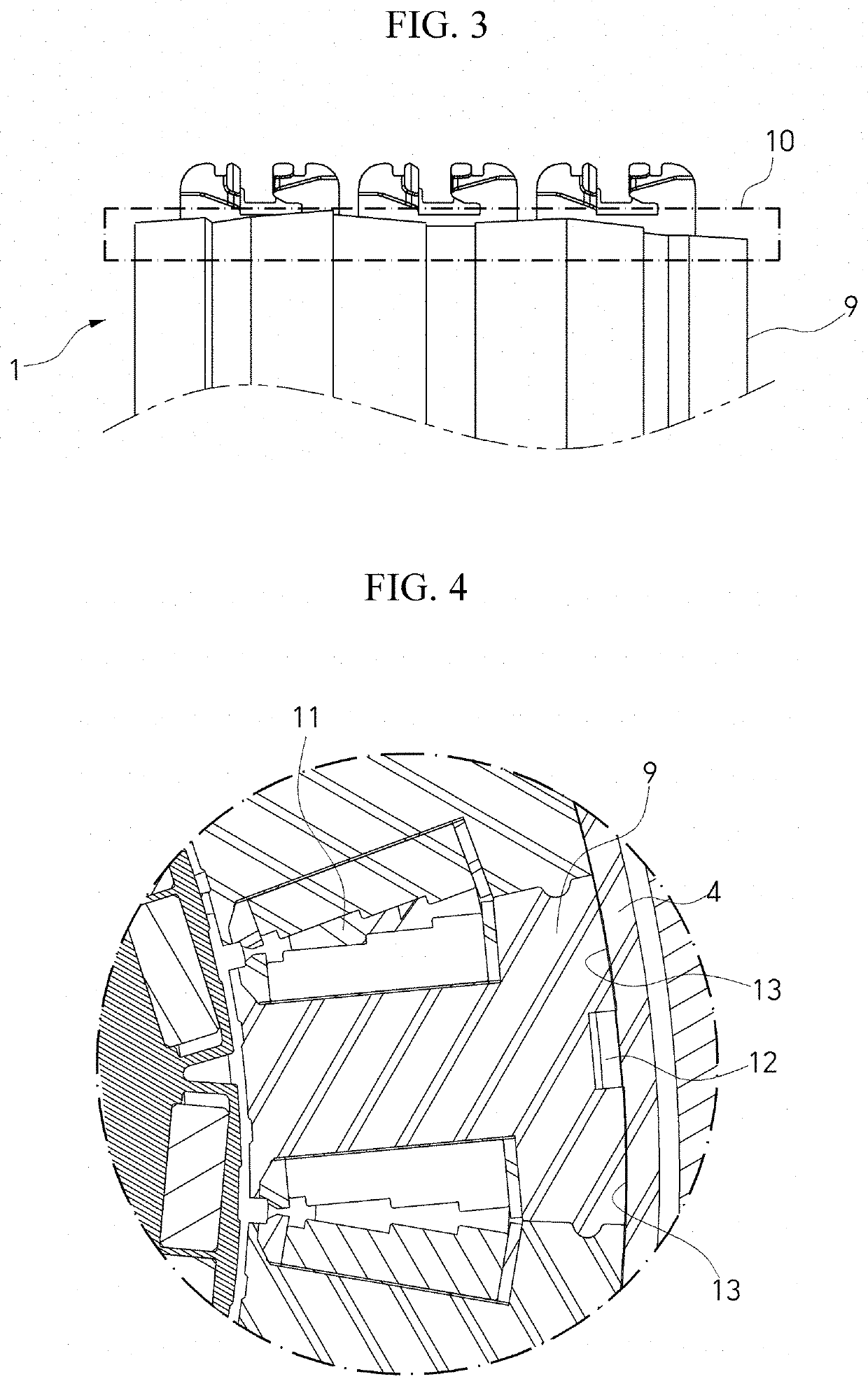
In addition, when an end of the stack portion 10 of the core is separated, since a distance from a terminal (not shown) assembled to the upper portion decreases, insulation defects may occur.
Moreover, a heat transfer area is small.

Method used


Image

  • Core-bobbin assembly and motor cooling method using the same
  • Core-bobbin assembly and motor cooling method using the same
  • Core-bobbin assembly and motor cooling method using the same

Examples


Embodiment Construction

[0029]Advantages and features of the present invention and methods of achieving the same will be clearly understood through embodiments described in detail with reference to the accompanying drawings. However, the present invention is not limited to the embodiments to be disclosed below but may be implemented in various different forms. The embodiments are provided in order to fully explain the present invention and fully explain the scope of the present invention for those skilled in the art. The scope of the present invention is defined by the appended claims. Meanwhile, the terms used herein are provided only to describe the embodiments of the present invention and not for purposes of limitation. Unless the context clearly indicates otherwise, the singular forms include the plural forms. It will be understood that the terms “comprise” or “comprising,” when used herein, specify some stated components, steps, operations and / or elements but do not preclude the presence or addition o...


PUM


Abstract

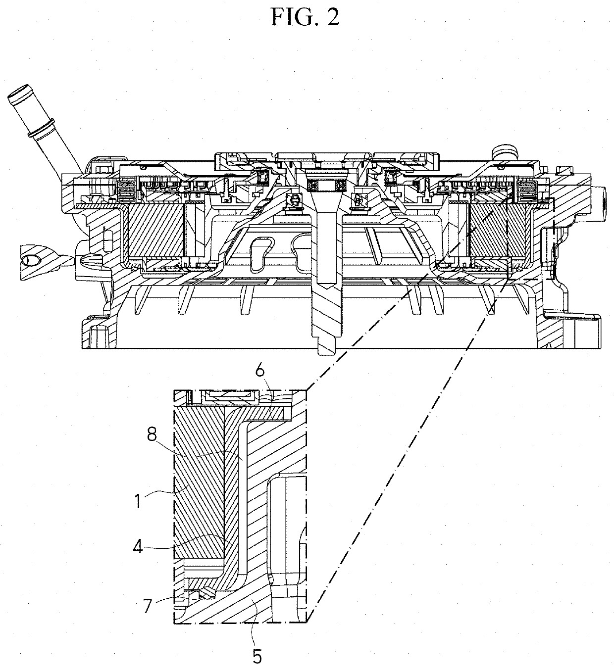
The present invention relates to an improved structure of a core-bobbin assembly without using a support ring, an O-ring, and a gasket which support and cool the core-bobbin assembly of a motor for a vehicle, so that a weight decreases, and a heat transfer area increases. The present invention also relates to a motor cooling method using the same. In the present invention, an outer circumference sheath (210) is added to a bobbin to cover an entirety of a core outer circumferential portion (110) including a cooling surface press-inserted into and in contact with a housing, that is, a recessed outer circumferential surface (120) formed on the core outer circumferential portion (110).

Description

CROSS-REFERENCE TO RELATED APPLICATION[0001]This application claims priority to and the benefit of Korean Patent Application No. 10-2019-0128566, filed on Oct. 16, 2019, the disclosure of which is incorporated herein by reference in its entirety.BACKGROUND1. Field of the Invention[0002]The present invention relates to a motor used in an eco-vehicle such as an electric vehicle (EV), a hybrid vehicle (HV), and a plug-in hybrid vehicle (PHV), and more specifically, to a core-bobbin assembly of a water-cooled motor and a motor cooling method using the same.2. Discussion of Related Art[0003]In a water-cooled motor for an eco-vehicle (electric vehicle (EV), a hybrid vehicle (HV), a plug-in hybrid vehicle (PHV), and the like), a coolant is injected using an injection nipple or pipe extending into the motor and the used coolant is discharged using a discharge nipple or pipe. Heat transfer using the injected coolant is performed while the injected coolant flows through a water passage formed...

Claims


Application Information

Patent Timeline
Patent Type & Authority Applications(United States)
IPC IPC(8): H02K1/20B60K1/00B60K11/02H02K1/14H02K3/52H02K9/19
CPCH02K1/20B60K1/00B60K11/02H02K2203/12H02K3/522H02K9/19B60K2001/006H02K1/146H02K1/148H02K2213/03B60Y2200/91B60Y2200/92B60Y2306/05H02K9/22Y02T10/62Y02T10/64H02K5/203H02K15/02H02K5/20
Inventor YANG, HYE SEONGSEO, YEONG WOOHWANG, SEONG JUNYIM, JUNG KYU
Owner HYUNDAI MOBIS CO LTD
Learn More