
Automatic System for the Conservation of Gas and other Substances

a technology of automatic system and gas, applied in the field of gas delivery, can solve the problems of constant flow of oxygen, waste of lives, and jeopardizing the health and safety of patients in need, and achieve the effect of saving lives

Pending Publication Date: 2021-04-01
OXFO CORP
View PDF0 Cites 0 Cited by
  • Summary
  • Abstract
  • Description
  • Claims
  • Application Information

AI Technical Summary

Benefits of technology

The invention is a system and method for supplying oxygen and other flowable substances to patients and other recipients in need. The goal is to save lives and maximize the effective use of available oxygen supplies. The system and method allow for an ample supply of oxygen on-demand while minimizing or eliminating inefficient oxygen losses.

Problems solved by technology

Meanwhile, in developing countries and during times of increased demand in all places, shortages of oxygen and excessive costs can place extreme limits on availability and can jeopardize the health and safety of patients in need.
For instance, during the COVID-19 pandemic that is ongoing during the writing of this document, the demand for oxygen has left hospitals and other caregiving institutions in dire need of the life-saving gas.
As a result, even while the patient exhales and thus cannot intake oxygen, the oxygen constantly flows and is wasted.
Indeed, half or even more of the constantly supplied oxygen in this continuous pressure feed method is wasted and expelled to the atmosphere.
The challenge is thus how to provide oxygen in sufficient supply on demand while minimizing waste.
However, certain conditions can prevent a person from getting enough oxygen.
Low blood oxygen may make patients feel short of breath, tired, or confused and can damage the patient's body.
In exigent circumstances, such as during an epidemic or a pandemic involving respiratory distress, need can dangerously outpace supply.
Moreover, in remote and economically challenged locations, providing ample replenishment of oxygen supplies can be highly costly, even catastrophically impossible.
Meanwhile, with life-saving oxygen in preciously short supply and with oxygen constantly passed through tubing to the patient, at least half of the supplied oxygen is simply exhausted into the atmosphere, including during exhalation during which the entirety of the supplied oxygen is wasted.
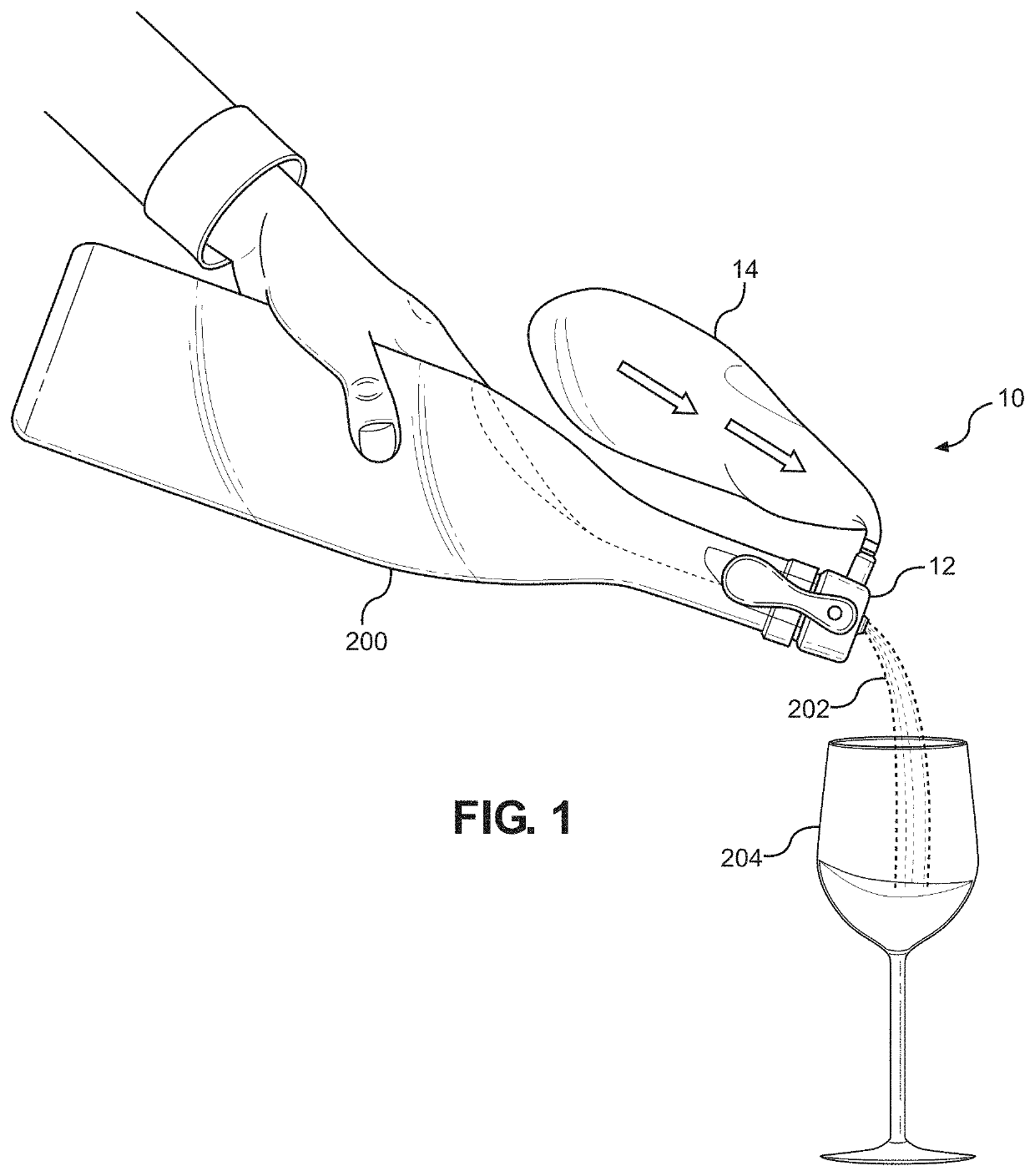
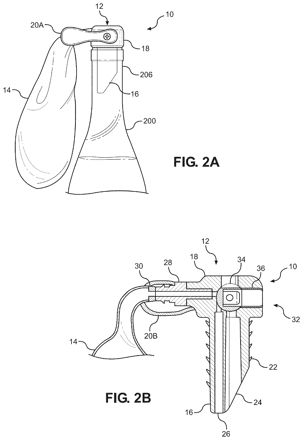
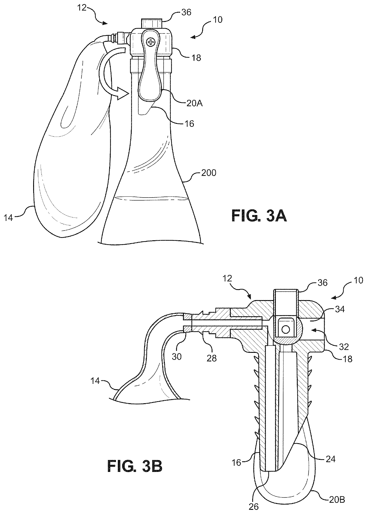
In these earlier disclosures, it was noted how preserving wines and other beverages and perishable substances once they have been initially exposed to air was long a problem that confronted consumers who want to utilize only a portion of the substance leaving the rest for a later occasion.
Unfortunately, as noted, most attempts of the prior art have failed without expensive and complicated pressurized systems.
For instance, due to its chemical composition, wine is susceptible to degradation by an increase in acidity and spoiling when it is exposed to a significant amount of undesired oxygen.
Indeed, to the experienced palate, oxygen typically produces a negative impact on the taste of wine within hours of oxygen exposure.
Although not overly difficult, such methods are of extremely limited effectiveness and reliability.
Each such method and system disadvantageously tends to introduce undesirable contaminants, such as dirt, oil, bacteria, fungi, and other contaminants, to the inner volume of the vessel.
The introduction of such contaminants runs directly counter to the goal of preserving the integrity of the contained wine or other substance and can itself contribute to spoilage while also representing a hazard to the health of the consumer.
Even beyond the undesirable insertion of a foreign object into what may be a very valuable bottle of wine, for instance, the system taught by Mahoney and many similar systems of the prior art still leave at some unadulterated, high-oxygen air in the vessel.
Moreover, an unintentional depressurization of the bulb, such as by leaking or another malfunction, will leave the contents of the vessel fully exposed to ambient air and consequent degradation.
However, inducing and maintaining a sufficient vacuum has typically proven challenging.
Furthermore, an indication of when adequate vacuum pressure has been achieved or lost is normally nonexistent.
Consequently, a user cannot be confident that the contents of the vessel are being preserved even when the process is initiated.
This and similar approaches can be challenging and expensive to implement and maintain such that they are outside the budget of many individual consumers.
Where too little gas is injected, the wine or other substance is inadequately protected.
Consequently, many users are tempted to inject an extra burst of gas, which is wasteful and dangerous.
Where too much gas is injected, excess pressure can accumulate in the bottle leading to leakage or even a dangerous bursting of the bottle.
Furthermore, the gas canisters used in such systems are typically disposable, which contributes to environmental waste.
Properly maintained, such systems do insulate the contents of the bottle from excess exposure to oxygen-rich ambient air, but the acquisition and maintenance costs and complexities leave the systems accessible only to restaurants and similar businesses and a limited set of individuals.
However, the present inventor appreciated that there are circumstances where continually refilling or replacing preservative gas within a compressible bladder can be inconvenient or where greater volumes of preservative gas may be required than can be practically retained in a bladder retaining a given volume of gas.
In these and other situations where there is a continual high demand for gas from the compressible reservoir, replenishing or replacing compressible gas in the reservoir can be impractical.
There are other circumstances where the reservoir may not have an inner volume sufficient in size to supply the preservative gas needed for preservation in a larger vessel.

Method used


Image

  • Automatic System for the Conservation of Gas and other Substances
  • Automatic System for the Conservation of Gas and other Substances
  • Automatic System for the Conservation of Gas and other Substances

Examples


Embodiment Construction

[0140]The automatic system for the conservation of gas and other substances, the systems and methods for preserving and dispensing wine and other perishable substances, and the automatic preservative gas replenishing system disclosed herein are subject to a wide variety of embodiments. However, to ensure that one skilled in the art will be able to understand and, in appropriate cases, practice the inventions disclosed herein, certain preferred embodiments of the broader inventions are described below and shown in the accompanying drawing figures.

[0141]Looking more particularly to the drawings, the structure and operation of an automatic gas conservation system 400 according to the present invention can be understood with reference to FIG. 46. As shown and described herein, the automatic gas preservation system 400 provides an on-demand supply of oxygen at ambient pressure to a recipient, such as a patient breathing mask 426, from a donor reservoir 404. The donor reservoir 404 retain...


PUM


Abstract

A system for conserving oxygen and other gasses supplied to a recipient. A supply conduit supplies gas from a source to a reservoir, which retains a volume of gas at ambient pressure. A conduit supplies gas from the reservoir to the recipient, and an inflation detection system detects when the reservoir is below a state of inflation and when the reservoir is inflated to the state of inflation. A valve system prevents gas from flowing from the source and into the reservoir when the reservoir is at the predetermined state of inflation, and the valve system permits gas to flow from the source and into the reservoir when the reservoir is below the predetermined state of inflation whereby gas within the reservoir can be continually replenished without pressurization above ambient pressure. The inflation detection system can be an electro-mechanical system. Alternatively, the inflation detection system can be a contactless system.

Description

RELATED APPLICATIONS[0001]This application is a Continuation-in-Part of application Ser. No. 16 / 358,666, filed Mar. 19, 2019, which was a continuation-in-part of application Ser. No. 15 / 057,117, filed Feb. 29, 2016, which was a continuation-in-part of application Ser. No. 14 / 211,137, filed Mar. 14, 2014, which claimed priority to Provisional Application No. 61 / 781,477, filed Mar. 14, 2013, and this application claims priority to Provisional Patent Application No. 63 / 056,944, filed Jul. 27, 2020. The entirety of each of the foregoing is incorporated herein by reference.FIELD OF THE INVENTION[0002]The present invention relates generally to the delivery of gases from a source to a recipient. More particularly, disclosed herein are a system and method for conserving gases and other substances when delivering them from a donor reservoir to a recipient by volumetric displacement at ambient pressure with automatic refilling of the donor reservoir from a source. In embodiments of the system...

Claims


Application Information

Patent Timeline
Patent Type & Authority Applications(United States)
IPC IPC(8): A61M16/00A61M16/20A61M16/08
CPCA61M16/0078A61M16/0084A61M16/208C12H1/12A61M2202/0208A61M2205/3341A23V2002/00A61M16/08B65D81/2076B65D81/2084B67D1/0885B67D3/048C12H1/14A61M16/06A61M16/202A61M2205/3331A61M2205/3379A61M2205/3306A61M16/107A61M2205/8206A61M2205/3334A61M2016/0033A61M2205/52A61M16/101A23L3/3409A61M16/0003A61M2016/0024
Inventor BAZOBERRY, CARLOS FERNANDOYOUNG, BRENT H.
Owner OXFO CORP
Learn More