
Heat sink having press-riveting structure

a heat sink and press-riveting technology, which is applied in the direction of lighting and heating apparatus, semiconductor/solid-state device details, laminated elements, etc., can solve the problems of poor heat sink seal, easy shaking or falling and difficult to ensure the stability of connection, so as to reduce the height of heat sink fins and improve heat dissipation efficiency

Inactive Publication Date: 2021-03-11
HUANG TSUNG HSIEN YUAN SHAN HSIANG
View PDF0 Cites 2 Cited by
  • Summary
  • Abstract
  • Description
  • Claims
  • Application Information

AI Technical Summary

Benefits of technology

The present invention provides a heat sink with a stable and secure structure which solves issues of existing heat sinks such as tilting and low heat dissipation efficiency. The heat sink fin is connected to the base with a connecting portion, ensuring stable support and reducing the height of the heat sink fin. The heat on the base can be directly transferred to the connecting portion, improving heat dissipation efficiency.

Problems solved by technology

Therefore, the clamping effect is not good and it is not easy to ensure its stable connection.
The heat sink fins may have different heights, and the heat sink fins are prone to shaking or falling.
With the riveting structure, the double-sided inflated plate cannot be attached to the base firmly, and the double-sided inflated plate is easily bent and deformed.
Besides, the contact area between the double-sided inflated plate and the base cannot be larger to improve heat dissipation efficiency.

Method used


Image

  • Heat sink having press-riveting structure
  • Heat sink having press-riveting structure
  • Heat sink having press-riveting structure

Examples


Embodiment Construction

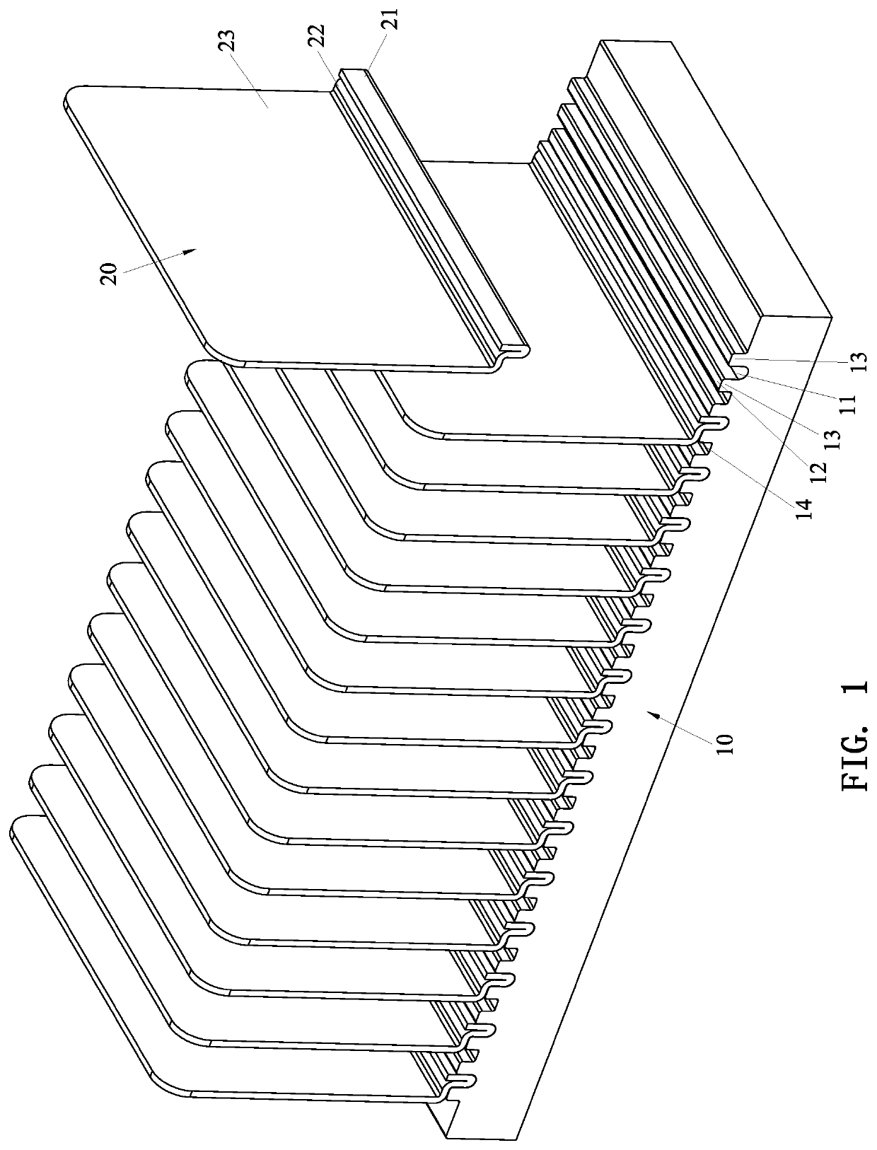
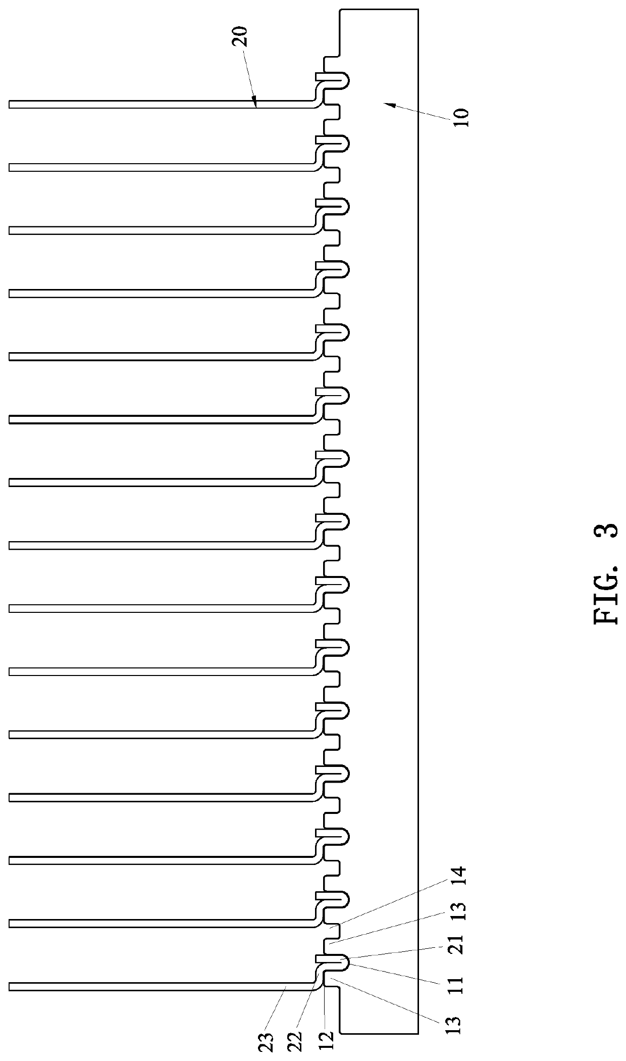
[0027]Referring to FIG. 1 through FIG. 6, a specific structure in accordance with a first embodiment of the present invention is shown, comprising a base 10 and a heat sink fin 20.

[0028]The surface of the base 10 is formed with a groove 11 for attachment of the heat sink fin 20. At least one side of the opening of the groove 11 has a contact surface 12. In this embodiment, the base 10 is made of copper, aluminum, copper-based alloy or aluminum-based alloy. A strip-shaped platform 13 is formed at either side of the groove 11. The contact surface 12 is located on the top surface of the strip-shaped platform 13. The contact surface 12 is a level surface, but not limited thereto, and may be a slope. The groove 11 is plural and arranged in parallel at intervals. The surface of the base 10 is recessed to form a concave groove 14 between every adjacent two of the grooves 11 to increase the heat dissipation area and improve the ventilation and heat dissipation effects.

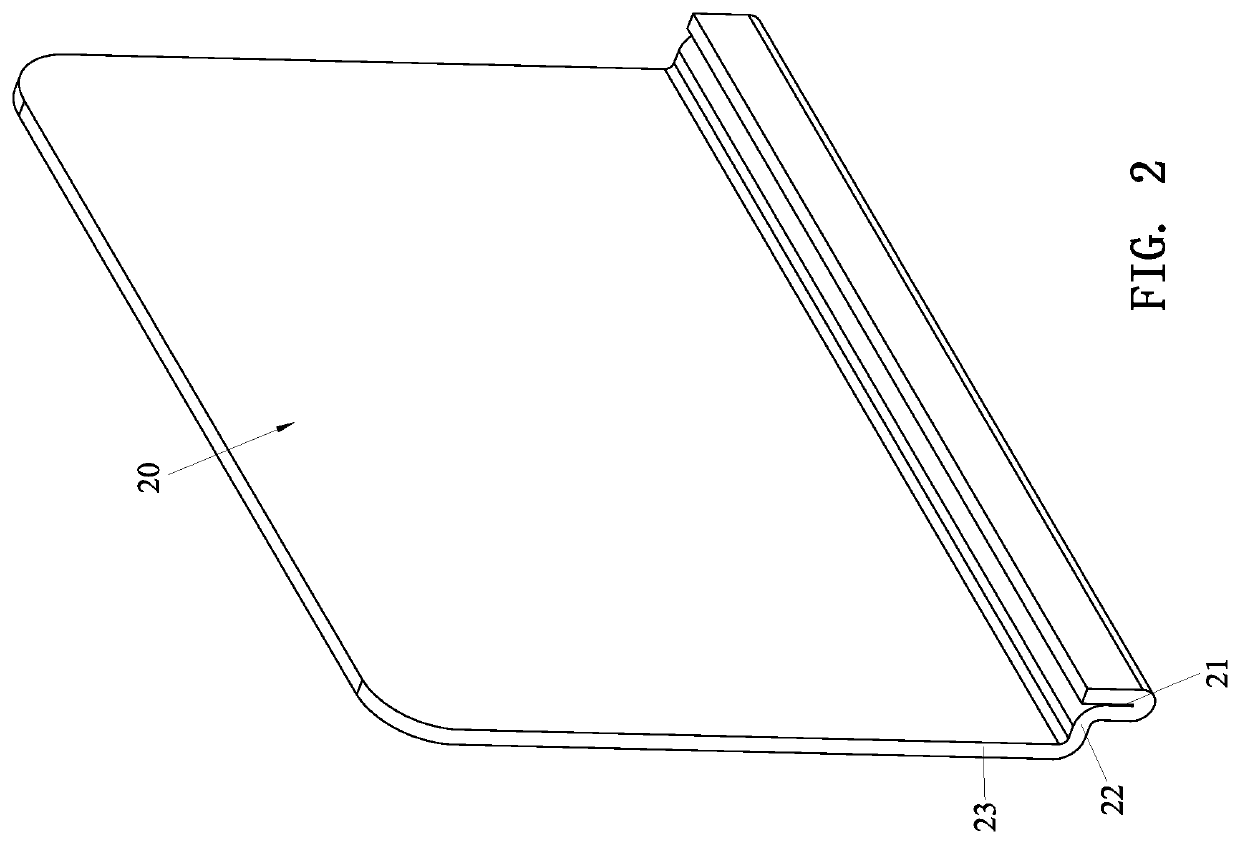
[0029]The heat sink fi...


PUM

PropertyMeasurementUnit
clamping forceaaaaaaaaaa
clamping forcesaaaaaaaaaa
heightsaaaaaaaaaa

Abstract

A heat sink having a press-riveting structure includes a base and a heat sink fin. The heat sink fin is formed with a connecting portion, and the connecting portion is in contact with a contact surface of the base. One side of the heat sink fin can be stably supported, and it is easy for a press head to thrust a folded insertion portion of the heat sink fin, so that the heat sink fin is combined with the base more reliably, and the height of the heat sink fin is reduced. The heat sink fin won't be bent and deformed easily.

Description

BACKGROUND OF THE INVENTION1. Field of the Invention[0001]The present invention relates to a heat sink, and more particularly to a heat sink having a press-riveting structure.2. Description of the Prior Art[0002]The heat sink fins and the base of a conventional heat sink are assembled together by soldering or by pressing. The heat sink fins are first inserted in preset grooves or clamping seat, and then pressed by a press head so that the heat sink fins are clamped and combined with the grooves (or the clamping seat) of the base. For example, as disclosed in U.S. Pat. No. 5,014,776, the respective two side walls of the grooves are pressed to cause a deformation to clamp the heat sink fins, such that the heat sink fins and the base are assembled together.[0003]In the above patent, through the deformation of both sides of the groove, the foot of the heat sink fin is clamped. However, the clamping force is concentrated at the deformation positions on both sides of the opening of the gr...

Claims


Application Information

Patent Timeline
Patent Type & Authority Applications(United States)
IPC IPC(8): F28F3/06H01L23/367B23P15/26
CPCF28F3/06F28D2021/0029B23P15/26H01L23/3672B23P11/005B23P2700/10H01L21/4882H01L23/427
Inventor HUANG, TSUNG-HSIEN
Owner HUANG TSUNG HSIEN YUAN SHAN HSIANG
Learn More