Bone-derived thermoplastic filament and method of manufacture

Pending Publication Date: 2021-01-28
ORTHOMOD LLC
View PDF0 Cites 0 Cited by
  • Summary
  • Abstract
  • Description
  • Claims
  • Application Information

AI Technical Summary

Benefits of technology

This patent describes a method and system for creating thermoplastic materials containing bone allograft. The bone is first mechanically processed to create a powder or fiber form, which is then mixed with a thermoplastic resin in a way that maximizes the amount of bone in the material while maintaining its strength. The mixture is then heated and forced through a die or mold to create the desired shape. The mixing can be done while the bone is in a heated state or in a cool allograft state. The resulting filament or pellet can then be sterilized and packaged for use in three-dimensional manufacturing processes. The system also uses solid mineral components to stabilize the bone proteins during the process, ensuring they don't denature during heating. Overall, this patent provides a way to create thermoplastic materials with bone allograft that have improved mechanical properties and can be used in various manufacturing processes.

Problems solved by technology

However, there are significant limitations to the application of natural bone allografts to such treatments.
Natural bone is available in limited anatomical shapes that may not be adequate for treatment of certain orthopedic pathologies.
The ability to machine or form bone is limited for similar reasons.
However, the heat required for manufacturing of raw material and final product limits the use of bioactive components into such devices.
Another common problem with allografts and implants of the past is the difficulty with which they can be manufactured with selective placement of bone in the implant or at predetermined or selected areas of the implant, such as bone-engaging surfaces of the implant.
One problem with manufacturing implants or allografts is the difficulty of getting bone material strategically located in areas of the implant where it is desired to have improved osteoconductivity, and potentially osteoinductivity, after the implant is implanted into a patient.
Unfortunately, ACB is only available in a limited number of circumstances.
Some individuals lack ACB of appropriate dimensions and quality for transplantation, and donor site pain and morbidity can pose serious problems for patients and their physicians.
One problem with processing these implants was that subjecting them to heat can have adverse effects on proteins in the bone.

Method used


Image

  • Bone-derived thermoplastic filament and method of manufacture
  • Bone-derived thermoplastic filament and method of manufacture
  • Bone-derived thermoplastic filament and method of manufacture

Examples


Embodiment Construction

[0173]Referring now to FIGS. 1-8D, a system 10, device, implant and processes for generating or creating a bone-derived thermoplastic and bone mixture that is adapted and processed to create a filament that is subsequently used to produce a device, such as an implant, is shown and will now be described. For ease of understanding, the system 10 will be described relative to FIGS. 1-4, with associated processes being described relative to FIGS. 5A-5B. The implant is described in detail relative to the examples in FIGS. 6A-8D.

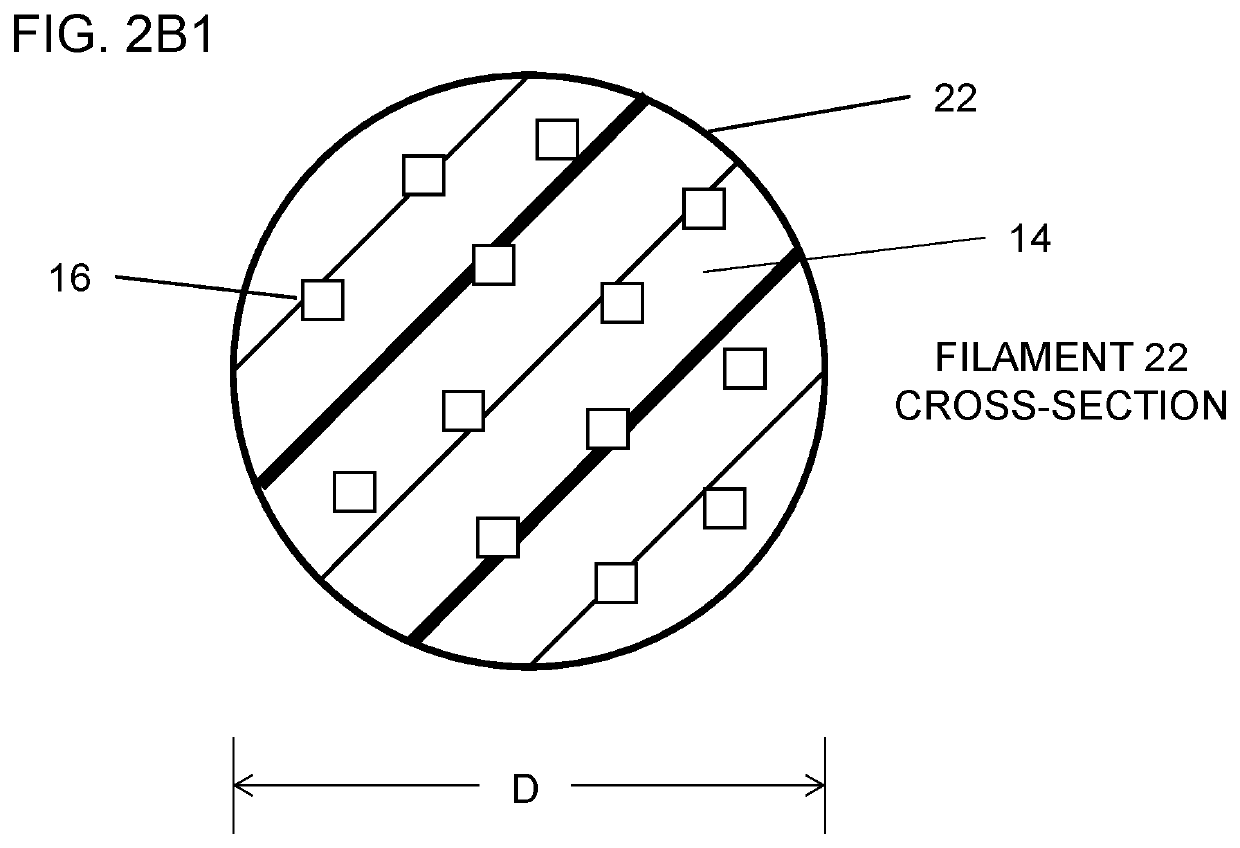
[0174]As best illustrated in FIG. 1, the system 10 comprises at least one or a plurality of stations for processing bone 16 and thermoplastic 14 together and, ultimately, to form a device / implant 26. A first station 12 includes a bone / thermoplastic processing and mixing station 12 for processing and / or mixing a thermoplastic 14 and bone 16 together. In general, the processing and mixing station 12 comprises multiple processes applied to the bone 16 to ensure prope...


PUM

PropertyMeasurementUnit
Fractionaaaaaaaaaa
Fractionaaaaaaaaaa
Percent by massaaaaaaaaaa

Abstract

A system, device / implant, method and processes for manufacturing a filament and an implant having at least one or a plurality of areas in the implant comprised of selectively-place bone to facilitate osteoconductivity and, potentially, osteoinductivity after the implant is implanted into a patient.

Description

CROSS-REFERENCE TO RELATED APPLICATION[0001]The present application claims priority to provisional U.S. Application Ser. No. 62 / 878,572 filed Jul. 25, 2019. This provisional application is incorporated herein by reference and made a part hereof.BACKGROUND OF THE INVENTION1. Field of the Invention[0002]This invention relates to a system and processes for manufacturing a bone-thermoplastic filament for use in manufacturing an implant having at least one or a plurality of areas in the implant comprised of bone to facilitate osteoconductivity, and potential osteoinductivity, after the implant is implanted into a patient.2. Description of the Related Art[0003]In the past, medical implants were commonly used during surgical procedures. Human-derived bone allografts are commonly used in the treatment of orthopedic pathologies and injuries. Such grafts have the benefits of consolidating into host bone and promoting healing through bony fusion or arthrodesis. However, there are significant l...

Claims


Application Information

Patent Timeline
IPC IPC(8): A61F2/30A61L27/36A61L27/44A61L27/54
CPCA61F2/30965A61L27/3608A61L27/44A61L27/54A61F2002/30065A61L2430/02A61L2430/38A61F2002/30957A61F2002/30968A61L27/3687A61F2/28A61F2/3094A61F2/4455A61F2002/2817A61F2002/2835A61F2002/30985A61F2310/00359A61F2310/00365A61F2310/00371B33Y10/00B33Y80/00A61L27/18A61L27/16A61F2/447A61F2002/30593A61F2002/3092A61F2002/30962B29C48/022B29C48/04B29C48/06B29C48/05B29K2101/12B29K2105/16A61F2/4644A61F2002/30136C08L77/00C08L69/00C08L33/12C08L33/20
Inventor KIRSCHMAN, DAVID LOUISWEEDA, DEWEY J.HUNTER, SHAWN A.
Owner ORTHOMOD LLC
Why Eureka
Try Eureka