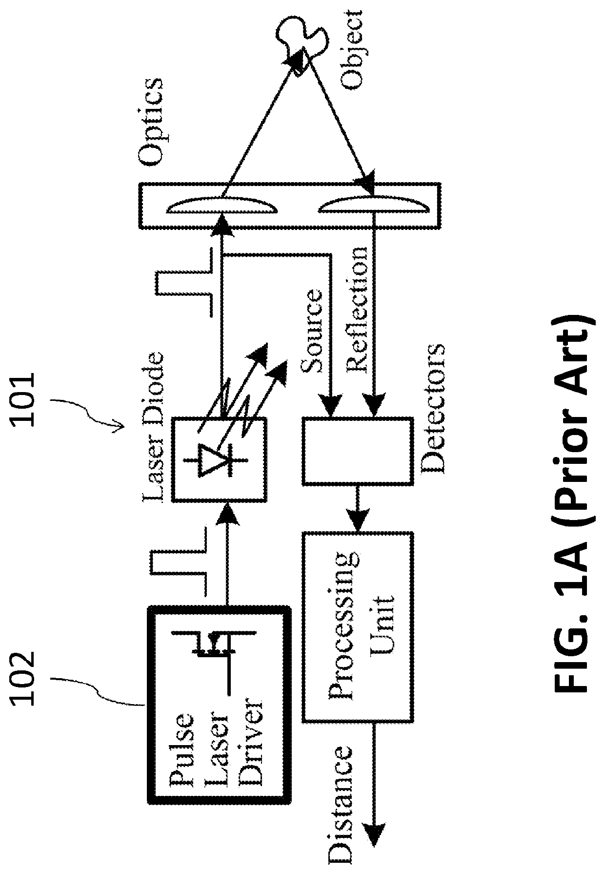
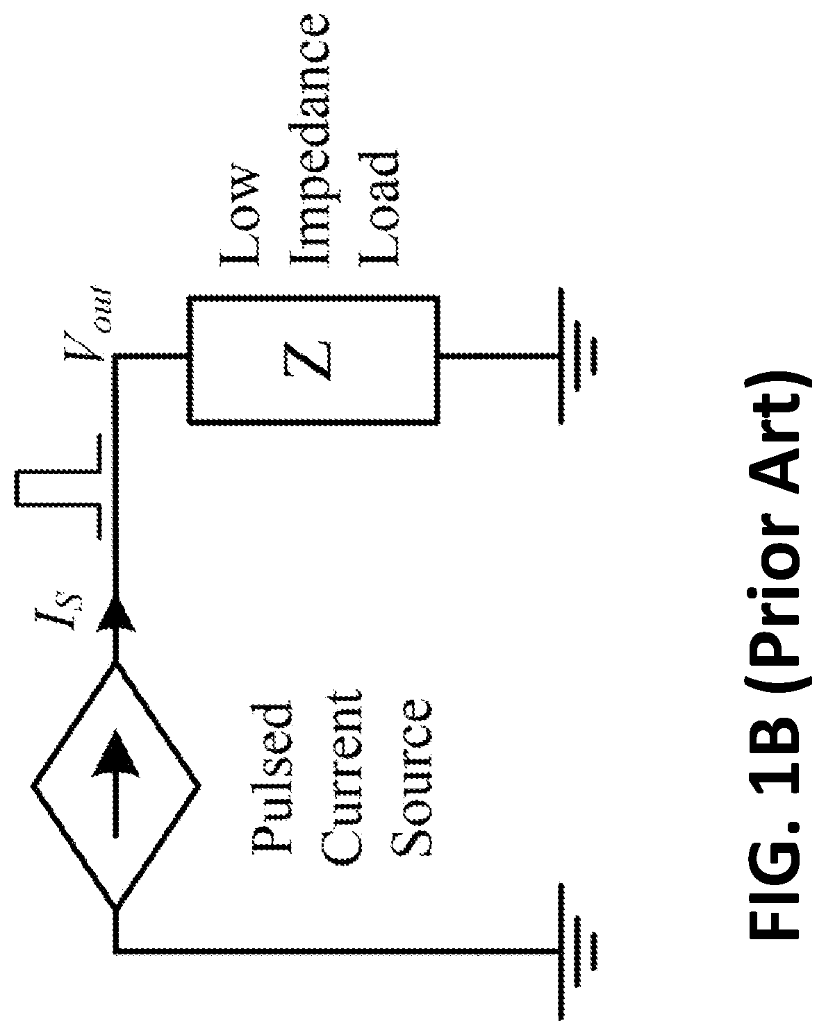
Low voltage sub-nanosecond pulsed current driver IC for high-resolution lidar applications
a low-voltage sub-nanosecond pulsed current and driver technology, applied in lasers, laser details, instruments, etc., can solve the problems of high-impedance source dynamic performance, rise-time and pulse width implementation, and extreme challenge, so as to reduce rise and fall times and narrow pulse width
- Summary
- Abstract
- Description
- Claims
- Application Information
AI Technical Summary
Benefits of technology
Problems solved by technology
Method used
Image

Examples
Embodiment Construction
[0060]Reference will now be made to embodiments of the present invention, examples of which are provided in the accompanying figures for purposes of illustration only. One skilled in the art will readily recognize from the following description that alternative embodiments of the structures and methods exemplified herein may be employed, mutatis mutandis, without departing from the principles of the invention.
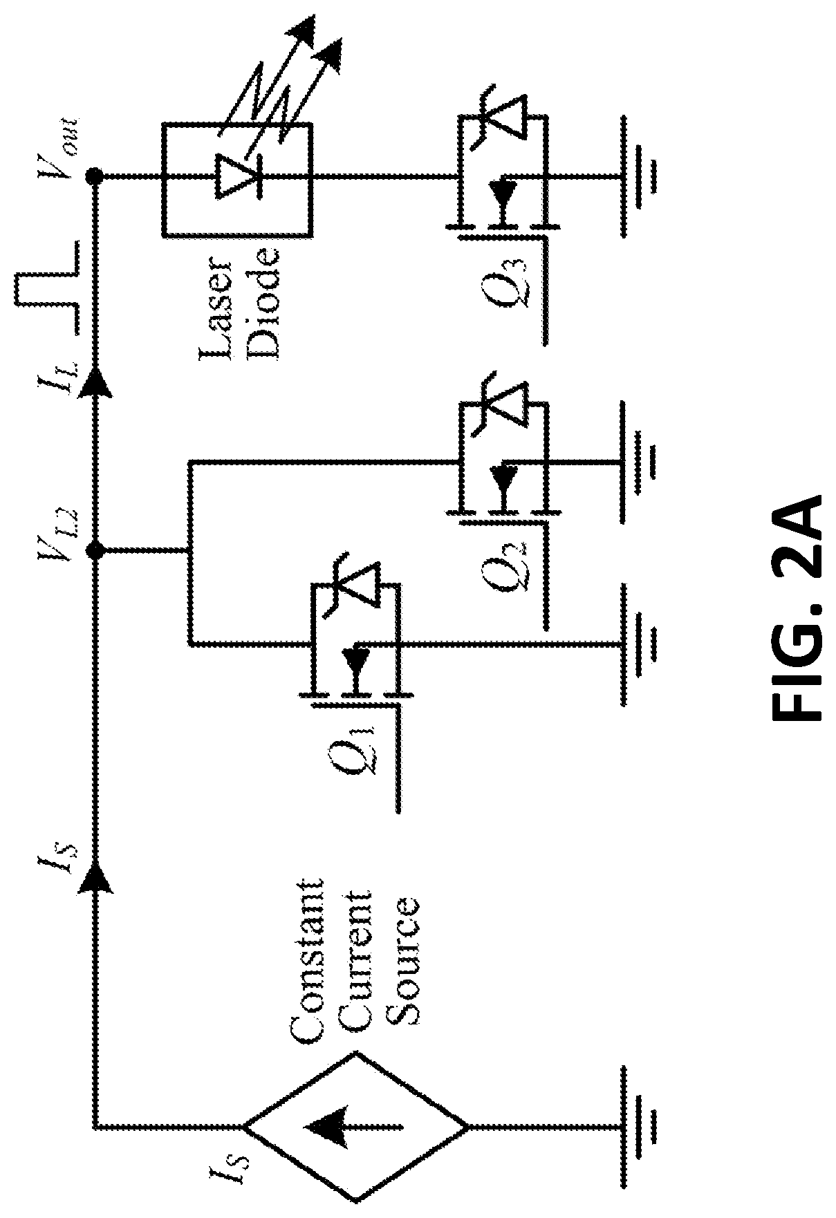
[0061]FIG. 2A shows a current driving concept, according to an embodiment of the present invention, utilizing a regulated constant current source 201 followed by a network of power switches, Q1, Q2 and Q3 that cooperatively act as a current routing network. The operation of the driver is described in FIG. 2B that illustrates an idealized gating sequence and load current. The operation is divided into an idle state and two phases: turning on and turning off transitions. In the idle state to, the switch Q1 is on, providing a closed path for the current flow of the source, while t...
PUM
 Abstract
Description
Claims
Application Information
 - R&D
- Intellectual Property
- Life Sciences
- Materials
- Tech Scout
- Unparalleled Data Quality
- Higher Quality Content
- 60% Fewer Hallucinations
Browse by: Latest US Patents, China's latest patents, Technical Efficacy Thesaurus, Application Domain, Technology Topic, Popular Technical Reports.
© 2025 PatSnap. All rights reserved.Legal|Privacy policy|Modern Slavery Act Transparency Statement|Sitemap|About US| Contact US: help@patsnap.com