Method of manufacturing a fuel cell module

a fuel cell module and manufacturing method technology, applied in the manufacture of final products, fuel cell details, electrochemical generators, etc., can solve the problems of low workability and the inability of the cell monitor connector to be inserted into the notch, and achieve the effect of improving the workability of the cell monitor connector and low workability

Active Publication Date: 2020-10-08
TOYOTA JIDOSHA KK
View PDF0 Cites 0 Cited by
  • Summary
  • Abstract
  • Description
  • Claims
  • Application Information

AI Technical Summary

Benefits of technology

The patent aims to improve the attachment of a cell monitor connector by improving workability. The technical effects of the patent include the use of a guide portion for positioning the connector, the elastic deformation of a projection portion for holding the connector, the use of an insulating sheet and a metal separator, and the rotation of an intermediate product for easier positioning. These features make the attachment process easier and more efficient.

Problems solved by technology

In the technique in the related art, if the positioning is displaced toward either one of the walls, the cell monitor connector and the either one of the walls interfere with each other, so that the cell monitor connector cannot be inserted into the notch.
On this account, it is necessary for an operator to position the cell monitor connector by taking the measure of a positional relationship between the cell monitor connector and the walls, and thus, workability is low.

Method used


Image

  • Method of manufacturing a fuel cell module
  • Method of manufacturing a fuel cell module
  • Method of manufacturing a fuel cell module

Examples


Embodiment Construction

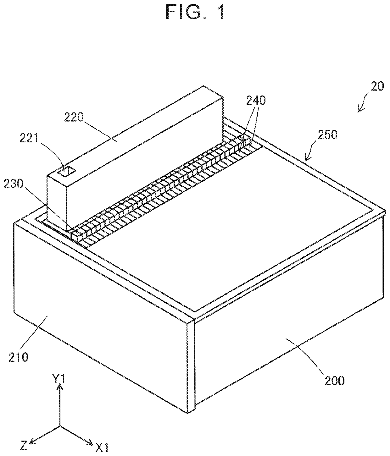
[0024]FIG. 1 is a perspective view illustrating a fuel cell module 20. The fuel cell module 20 includes a case 200, an end plate 210, a cell monitor 220, a plurality of cell monitor connectors 230, and a plurality of cells 240. All the cells 240, the case 200, and the end plate 210 are also collectively referred to as an intermediate product 250.

[0025]The cells 240 are accommodated in the case 200. The cell monitor 220 is fixed to an upper part of the case 200. Each of the cell monitor connectors 230 is a component electrically connected to a corresponding cell 240 for a fuel cell so as to measure a power generation voltage. Each of the cell monitor connectors 230 is connected to the cell monitor 220 via a cable 239 (FIG. 7, and so on).

[0026]An X1-Y1-Z coordinate system that is a right-handed rectangular coordinate system is defined as illustrated in FIG. 1. A Z-X1 plane is parallel to a horizontal plane. A positive side in a Y1-direction indicates an upper side in a vertical direct...


PUM

PropertyMeasurementUnit
widthaaaaaaaaaa
distanceaaaaaaaaaa
power generation voltageaaaaaaaaaa

Abstract

A cell monitor connector is inserted with a first surface following a guide portion. When the cell monitor connector is further inserted, the cell monitor connector makes contact with a projection portion. In a state where the attachment is completed, the projection portion is elastically deformed so as to press a second surface. Due to this force, the cell monitor connector is held such that it is sandwiched between the projection portion and the guide portion.

Description

[0001]INCORPORATION BY REFERENCE[0002]This is a divisional application of U.S. patent application Ser. No. 16 / 157,620, filed Oct. 11, 2018, which claims the disclosure of Japanese Patent Application No. 2017-202365 filed on Oct. 19, 2017 including the specification, drawings and abstract which are all incorporated herein by reference in their entirety.BACKGROUND1. Technical Field[0003]This disclosure relates to an attachment method of a cell monitor connector to a cell of a fuel cell and a fuel cell module.2. Description of Related Art[0004]Japanese Unexamined Patent Application Publication No. 2013-120655 (JP 2013-120655 A) describes a technique in which a notch is provided in a corner of a frame member constituting a cell of a fuel cell, and a cell monitor connector is attached, by insertion, to a separator exposed from the notch. In a state where the cell monitor connector is attached, the notch includes walls between which opposite side surfaces of the cell monitor connector are...

Claims


Application Information

Patent Timeline
Patent Type & Authority Applications(United States)
IPC IPC(8): H01M8/0202H01M8/00H01M8/0273
CPCH01M8/0206H01M8/006H01M8/0202H01M8/04313H01M8/0273H01M8/04664H01M8/04671H01M8/04686Y02E60/50Y02P70/50
Inventor SUGITA, KAZUMI
Owner TOYOTA JIDOSHA KK
Why Eureka
Try Eureka