


Quick Research
Generate reliable direction feasibility study reports for your R&D in just a few steps.

Technical Q&A
Discover and master advanced knowledge NOW. Basics, ideas, possibilities, all at once.

Find Solutions
As an expert in R&D theories, this can generate solutions to your technical problems instantly.

Evaluate Feasibility
Analyze your overall solution with one click, know your potential R&D risks in advance.

Monitor Landscape
Get weekly tech updates, stay abreast of the latest tech innovations and key insights.
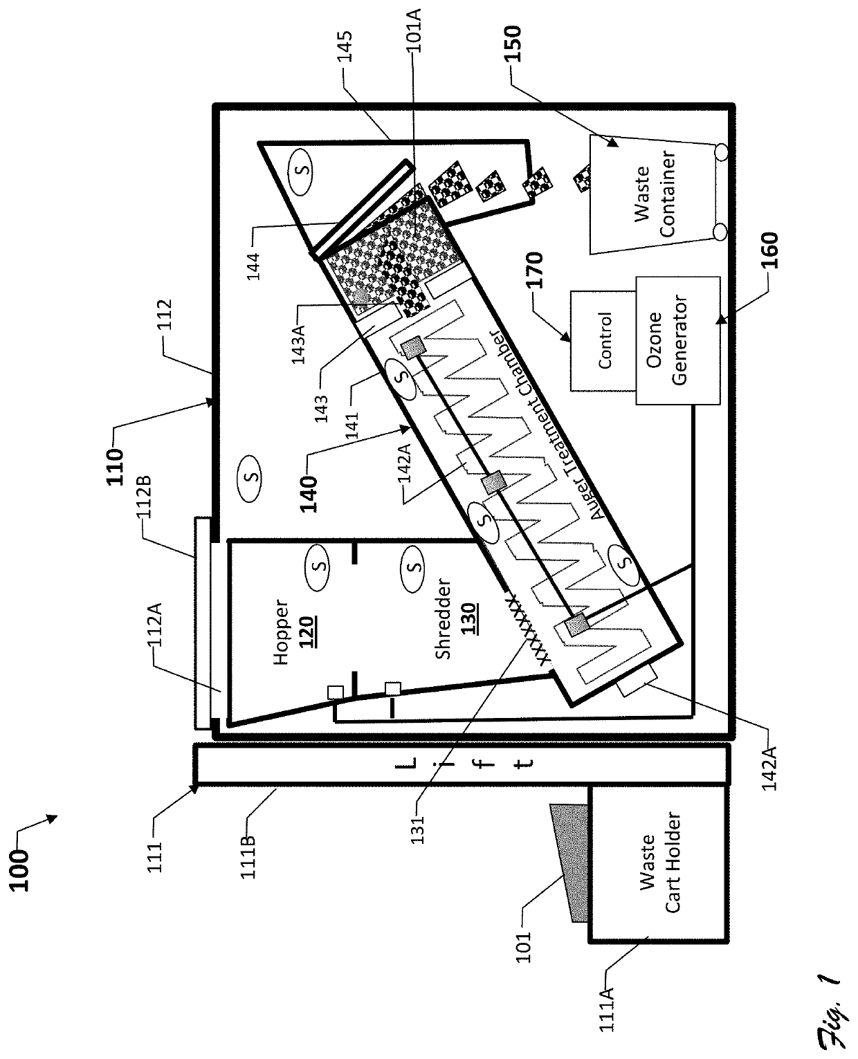
Small-Footprint Systems, Components, and Methods for Sterilizing Medical Waste
a technology of medical waste and small footprint, applied in the field of medical waste treatment, can solve the problems of posing additional risks to waste management workers and the environment, the waste-processing speed (throughput) is less than desirable for some medical facilities, and the cost of incineration and autoclaving is high. to achieve the effect of facilitating the maintenance of pressure and ozone concentration
- Summary
- Abstract
- Description
- Claims
- Application Information
AI Technical Summary
Benefits of technology
Problems solved by technology
Method used
Image

Examples
Embodiment Construction
[0018]This document, which includes the referenced drawings and appended claims, describes one or more specific embodiments of one or more inventions. These embodiments, offered not to limit but only to exemplify and teach the invention(s), are shown and described in sufficient detail to enable those skilled in the art to implement or practice the inventions. Thus, where appropriate to avoid obscuring the invention, the description may omit certain information known to those of skill in the art. This description also incorporates the disclosures of U.S. Pat. Nos. 8,518,339; 8,652,405; and 8,784,746 herein by reference.
[0019]This document may use relational terms, such as second, top and bottom, and the like. These terms may be used solely to distinguish one entity or action from another entity or action without necessarily requiring or implying any actual such relationship or order between such entities or actions. The terms “comprises,”“comprising,”“has”, “having,”“includes”, “incl...
PUM
 Abstract
Description
Claims
Application Information
 - R&D Engineer
- R&D Manager
- IP Professional
- Industry Leading Data Capabilities
- Powerful AI technology
- Patent DNA Extraction
Browse by: Latest US Patents, China's latest patents, Technical Efficacy Thesaurus, Application Domain, Technology Topic, Popular Technical Reports.
© 2024 PatSnap. All rights reserved.Legal|Privacy policy|Modern Slavery Act Transparency Statement|Sitemap|About US| Contact US: help@patsnap.com