[0007]An example internal combustion engine in accordance with the present invention may have the
advantage that the exhaust gas may be recirculated to the fresh-air side of the internal combustion engine without the need for increasing the fuel consumption of the internal combustion engine and / or, if a charging device is provided, the necessary charger output. This is achieved according to the present invention in that the
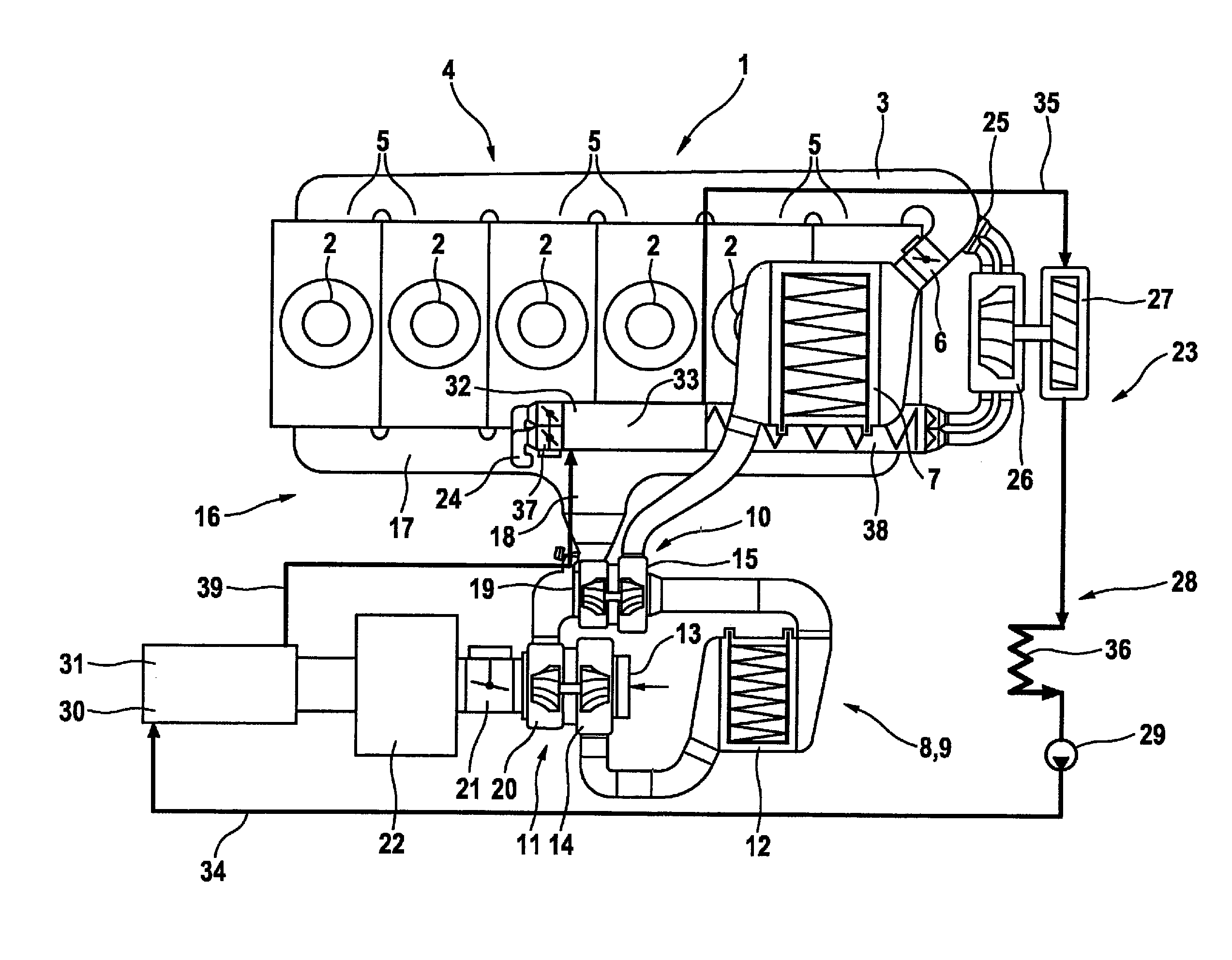
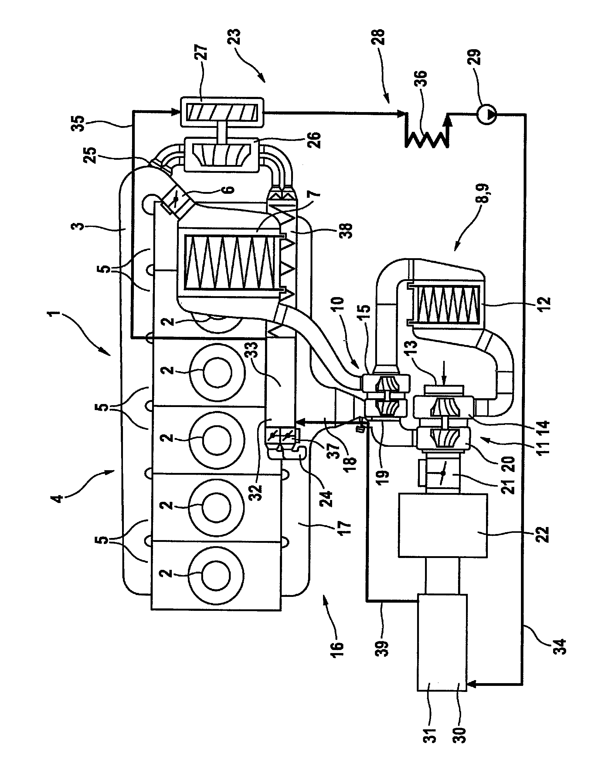
exhaust gas recirculation device has at least one compressor for compressing the exhaust gas which is supplied to the fresh-air side of the internal combustion engine. The compressor is used for compressing, i.e., for a pressure boost, of the exhaust gas. For this purpose, the compressor is assigned to the
exhaust gas recirculation device, i.e., it compresses the exhaust gas before it reaches the fresh-air side of the internal combustion engine, where it mixes with the
fresh air which is supplied to the internal combustion engine. The compressor is situated directly in an exhaust gas recirculation line in which the recirculated exhaust gas prevails exclusively. The exhaust gas recirculation device is thus a unit which is present separately from the fresh-air side. The compressor is consequently not the compressor of a possibly provided charging device of the internal combustion engine. The recirculated exhaust gas is rather compressed before it reaches the fresh-air side, i.e., before it is combined with the
fresh air. The compressor of the exhaust gas recirculation device allows the exhaust gas to be supplied to the fresh-air side downstream from a compressor of the charging device because the exhaust gas is already at a sufficiently
high pressure level. With the aid of the compressor, the pressure of the exhaust gas is boosted, whereby a larger amount of the exhaust gas may be brought to the fresh-air side and may thus be resupplied to the internal combustion engine.
[0008]One refinement of the present invention provides
thermal energy, which has been extracted from the exhaust gas, for operating the compressor. This embodiment variant allows for a particularly energy-efficient operation of the compressor. The
thermal energy is present in the exhaust gas anyway and would be discharged unused into a surrounding of the internal combustion engine if it is not used to operate the compressor. The amount of the recirculated exhaust gas may thus be increased without increasing the fuel consumption of the internal combustion engine or the need for providing a greater output of the charging device. For extracting the
thermal energy from the exhaust gas, a steam cycle may be provided.
[0011]One refinement of the present invention provides that the compressor is situated downstream or upstream from the at least one exhaust
gas cooler. The exhaust
gas cooler is used to cool the exhaust gas either upstream from the compressor or downstream from the compressor. Cooling the exhaust gas increases the effect of the exhaust gas recirculation device, since the combustion temperature in the internal combustion engine may be further decreased in this way. The compressor is preferably situated downstream from the exhaust
gas cooler because the
thermal load of the compressor is reduced in this way, and the necessary compressor output is reduced due to the higher density of the cooler exhaust gas. Fundamentally, the compressor may, however, also be situated upstream from the exhaust gas cooler because the
heat transfer within the exhaust gas cooler is improved due to the higher temperature of the compressed exhaust gas and the compressor may thus have a smaller design.
[0014]One refinement of the present invention provides that an exhaust gas extraction connector for extracting the exhaust gas, which was supplied to the internal combustion engine, is situated downstream or upstream from the exhaust gas
turbocharger. The exhaust gas may thus be extracted from the exhaust gas
system of the internal combustion engine before it flows through the exhaust gas
turbocharger or only after that. Placing the exhaust gas extraction connector upstream from the exhaust gas
turbocharger is preferred. At this point, the exhaust gas still has a relatively
high pressure level, for which reason relatively low output is required for compressing the exhaust gas in the exhaust gas recirculation device. Additionally, the exhaust gas temperature is higher than if it were downstream from the exhaust gas turbocharger, so that a
heat exchanger which is situated at this place may be optimally used to generate steam. In this way, a
superheating of the steam may, for example, be carried out. Alternatively, the exhaust gas extraction connector may, however, be situated downstream from the exhaust gas turbocharger. The
advantage here is that the exhaust gas extraction does not reduce the output of the exhaust gas turbocharger.
