Large diameter plethysmograph

Active Publication Date: 2007-08-02
DATA SCI INT
View PDF10 Cites 8 Cited by
  • Summary
  • Abstract
  • Description
  • Claims
  • Application Information

AI Technical Summary

Benefits of technology

[0017] The combination of the flanges and O-ring is highly effective in producing an airtight seal. In fact, the seal can be so effective that opening of the test chamber can be difficult with larger plethysmographs, e.g., when the diameter of the test chamber is greater than about six inches. This difficulty is addressed by the present invention by slightly tapering one of the flange interior faces toward the end of the flange so that the spacing between the flange faces is greater at the end of the tapered flange than at the base of the tapered flange. Therefore, as the chamber is opened the pressure against the O-ring quickly diminishes facilitating opening of the chamber.
[0020] The reference and test chambers each include restricted airflow openings to permit air to flow to and from the chambers. The airflow opening may be a pneumotach or pneumotachograph, which is basically a restricted airflow opening that may include a screen covering the opening to create a pressure drop. Preferably, these airflow openings communicate with the exterior of the plethysmograph through a common inlet as described in the '532 patent noted above to reduce background noise resulting from differences in the air pressure to the chambers.
[0021] As described in the '532 patent, the chambers may communicate with the exterior through a manifold which includes airflow openings to the chambers and an exterior airflow opening, with passageways connecting the exterior opening to the chamber airflow openings. Preferably, the length of the passageways from the exterior airflow opening to the chamber airflow openings are approximately equal to minimize differences in timing and resultant noise. In the present plethysmograph, the manifold is preferably mounted on the top of the reference chamber. As will be described in detail hereinafter, a mounting block may be secured to the top of the reference chamber with the noise reduction manifold being attached to the mounting block. Passageways then extend through the mounting block from the airflow openings in the manifold to the chambers.

Problems solved by technology

This non-chamber originated air pressure variation, known as background noise or simply noise, can adversely affect the accuracy of the recorded data, since the transducer also measures the noise.

Method used


Image

  • Large diameter plethysmograph
  • Large diameter plethysmograph
  • Large diameter plethysmograph

Examples


Embodiment Construction

[0029] In the following description, terms such as horizontal, upright, vertical, above, below, beneath, and the like, are used solely for the purpose of clarity in illustrating the invention, and should not be taken as words of limitation. The drawings are for the purpose of illustrating the invention and are not intended to be to scale.

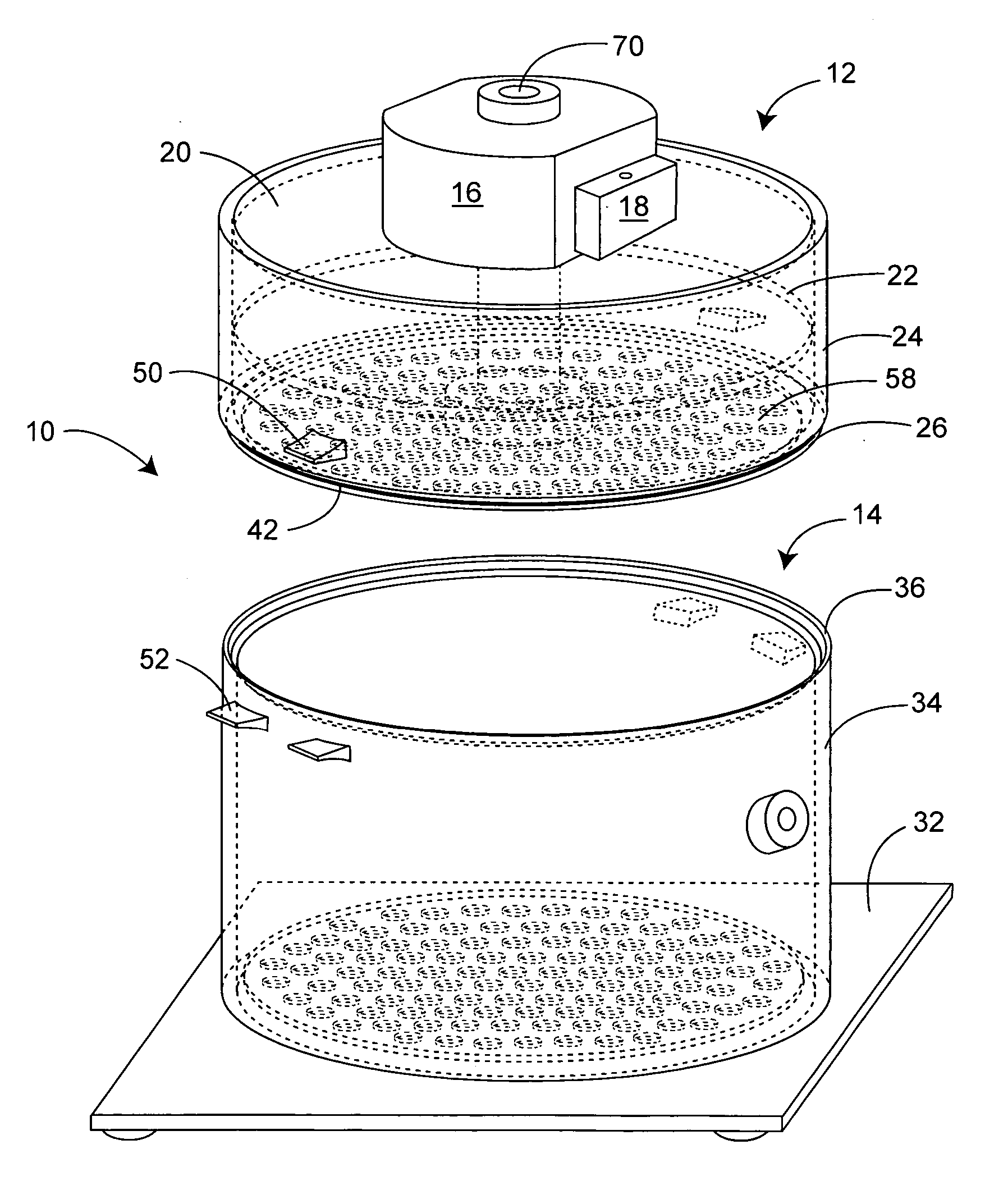
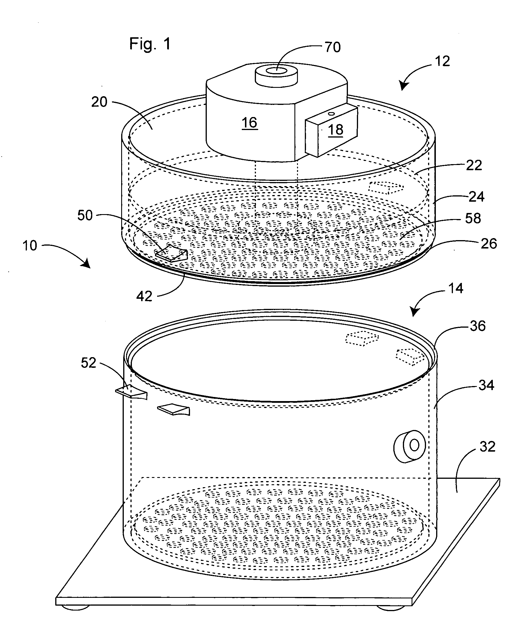
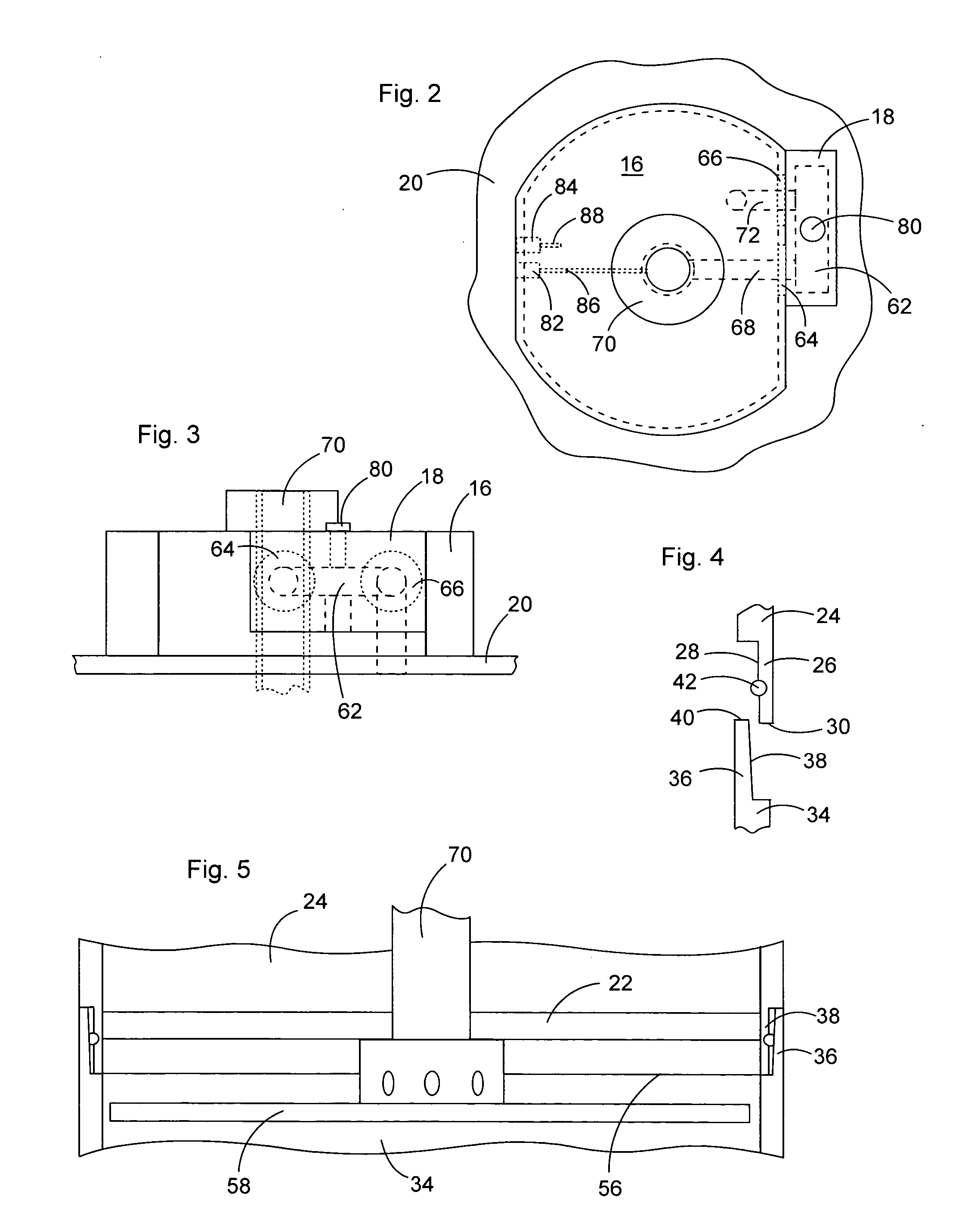
[0030] As best illustrated in FIG. 1, a preferred plethysmograph, generally 10, is comprised of a reference chamber, generally 12, an open-top test chamber, generally 14, and mounting block 16 supporting noise reduction manifold 18.

[0031] Reference chamber 12 is comprised of a top wall 20, a bottom wall 22, and a continuous side wall 24 extending around the peripheries of top wall 20 and bottom wall 22. The lower edge of side wall 24 extends below bottom wall 22 and includes a downwardly extending continuous flange 26 that has an interior face 28 and a lower edge 30.

[0032] Test chamber 14 is comprised of a footed base 32 with an upper surface act...


PUM


Abstract

A plethysmograph is described that includes a reference chamber having a top wall, a bottom wall, a barrier wall spaced beneath the bottom wall, a continuous side wall having a lower edge, and a first continuous flange with a lower edge below the bottom wall and above the barrier wall; a test chamber having a bottom wall, a continuous side wall with an upper edge, and a second continuous flange extending upwardly from the upper edge, the interior face of one of the flanges including an annular groove with an O-ring in the groove, and the interior face of the other flange being tapered from vertical by up to about 1°; and a manifold having airflow openings in communication with the reference and test chamber and a common exterior airflow opening through a passageway, and a sampling port in communication with the passageway.

Description

BACKGROUND OF THE INVENTION [0001] (1) Field of the Invention [0002] The present invention relates to plethysmographs used to measure changes in air volume, such as in non-invasive pulmonary testing of small animals, and in particular to larger plethysmographs that provide a test chamber with an airtight seal without the use of clamps, but which can be readily opened when desired. The invention further relates to a reduced noise plethysmograph that include means for air sampling. [0003] (2) Description of the Prior Art [0004] Plethysmographs are used in research to collect data relating to changes in air pressure within a test chamber. An example of such data is pulmonary data from small animals, such as mice. Most plethysmographs are comprised of a test chamber to enclose the test subject, a reference chamber, and a differential pressure transducer connected to the two chambers, e.g., via tubing extending from a port in each chamber to the transducer. Both chambers are in communica...

Claims


Application Information

Patent Timeline
IPC IPC(8): A61B5/08
CPCA61B2503/40A61B5/0806
Inventor SHEEHAN, VITOLARSON, RICHARD A.
Owner DATA SCI INT
Why Eureka
Try Eureka