Neural network device, signal generation method, and program
a neural network and signal generation technology, applied in biological neural network models, instruments, computing, etc., can solve problems such as increasing calculation time, and achieve the effect of curtailing an increase in calculation tim
- Summary
- Abstract
- Description
- Claims
- Application Information
AI Technical Summary
Benefits of technology
Problems solved by technology
Method used
Image
Examples
first embodiment
Conclusion of First Embodiment
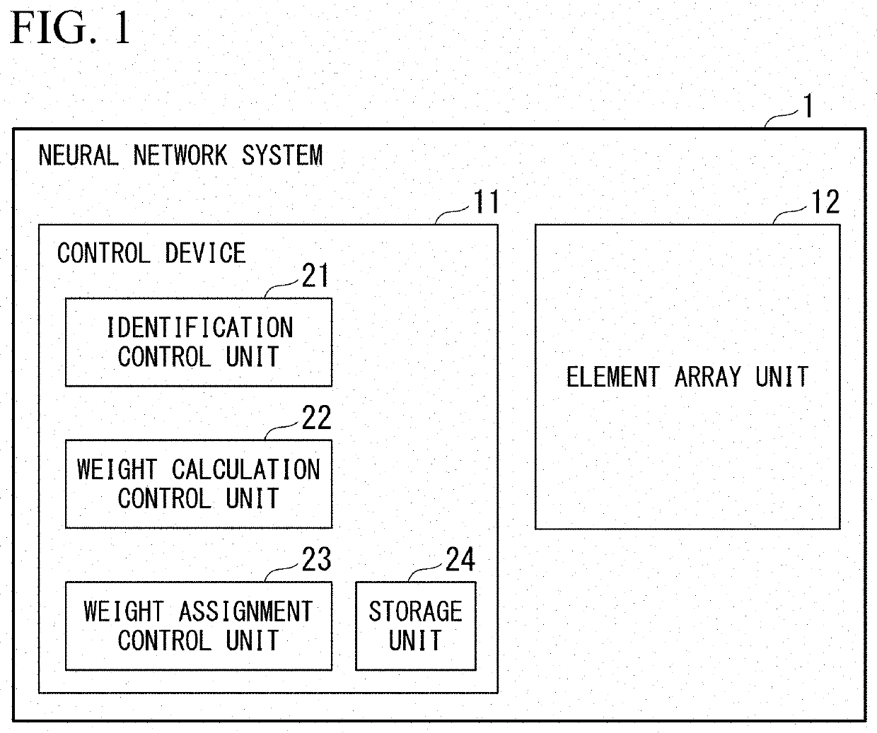
[0274]As described above, in a configuration in which the weight (connection weight) is realized by a neuromorphic element having a finite resolution in the neural network system 1 according to the embodiment, an appropriate discretization step size is determined on the basis of a case in which the true value of the connection weight obtained by the real number simulator or the like with precision higher than the resolution is used and a case in which the discretization step size set for the characteristics of the neuromorphic element is used. Further, the dynamic range (the width of the dynamic range) is determined on the basis of the determined discretization step size and the resolution. Further, the dynamic range (the width and the offset amount of the dynamic range, the upper limit value, and the lower limit value) is determined on the basis of the offset amount (0 or a value other than 0) of the dynamic range.
[0275]In the neural network system 1 a...
second embodiment
[0287]Hereinafter, a second embodiment of the present invention will be described with reference to FIGS. 14 to 27.
[Overview of Neural Network Device]
[0288]FIG. 14 is a diagram illustrating a schematic configuration of a neural network device 300 according to the second embodiment of the present invention.
[0289]The neural network device 300 includes a sensing device 310, an AD converter 320, a decimation circuit 330, a threshold value acquisition unit 340, a PWM modulation circuit 350, a neuromorphic device 360, and a current integration circuit 370.
[0290]The sensing device 310 can be configured of various sensors. As an example, the sensing device 310 includes an imaging element such as a charge-coupled device (CCD) image sensor or a complementary MOS (CMOS) image sensor, and outputs an image signal according to an amount of incident light. In this example, the sensing device 310 samples an image at a predetermined number of pixels or in a frame period, and outputs a pixel value of...
modification example (
PART 3)
[0353]FIG. 23 is a diagram illustrating a second modification example of the threshold value th that is referred to by the decimation circuit 330 of the embodiment.
[0354]FIG. 24 is a diagram illustrating a second modification example of the discrete value conversion in the decimation circuit 330 of the embodiment.
[0355]In the above-described embodiment, the input discrete value IDV is divided (for example, divided into four) depending on a plurality of threshold values th (see FIGS. 15 and 16). The modification example is different from the above-described embodiment in that the input discrete value IDV is divided into two depending on a single threshold value th.
[0356]That is, the decimation circuit 330 of the modification example generates a binary decimation signal DS by dividing the quantization step number of the input signal IS into two. In a specific example illustrated in FIG. 23, a threshold value th21 for dividing the quantization step number (256 steps) of the inpu...
PUM
 Abstract
Description
Claims
Application Information
 - R&D
- Intellectual Property
- Life Sciences
- Materials
- Tech Scout
- Unparalleled Data Quality
- Higher Quality Content
- 60% Fewer Hallucinations
Browse by: Latest US Patents, China's latest patents, Technical Efficacy Thesaurus, Application Domain, Technology Topic, Popular Technical Reports.
© 2025 PatSnap. All rights reserved.Legal|Privacy policy|Modern Slavery Act Transparency Statement|Sitemap|About US| Contact US: help@patsnap.com


