
Cell capture apparatus

a cell capture and apparatus technology, applied in the field of cell capture apparatuses, can solve the problems of adversely affecting analysis, difficult dielectrophoresis of ctcs in blood, and regard to the capture of other types of large cells having a larger size, so as to achieve isolation and reduce contamination

Active Publication Date: 2020-09-10
NOK CORP +1
View PDF0 Cites 2 Cited by
  • Summary
  • Abstract
  • Description
  • Claims
  • Application Information

AI Technical Summary

Benefits of technology

The present invention is a cell capture apparatus that can isolate large cells from a liquid sample and transfer them to a carrier liquid with minimal contamination. The apparatus uses a cell-separation flow passage to separate large and small cells from the liquid sample and carrier liquid. A cell capture unit fixes the large cells and carrier liquid, where multiple large cells are captured using dielectrophoresis. The unified cell separation unit and cell capture unit reduces contamination when transferring the separated cells to the capture unit.

Problems solved by technology

The reason for replacing the liquid is that dielectrophoresis is difficult for CTCs in blood since the electroconductivity of normal blood is almost the same as that of CTCs.
In addition, even if CTCs are isolated, CTCs may be contaminated before CTC capture processing, which may adversely affect analysis results.
Although problems related to capture of CTCs have been described, there are similar problems with regard to the capture of other types of large cells having sizes larger than other cells.

Method used


Image

  • Cell capture apparatus
  • Cell capture apparatus
  • Cell capture apparatus

Examples


Embodiment Construction

[0044]Hereinafter, with reference to the accompanying drawings, an embodiment according to the present invention will be described. It is noted that the drawings do not necessarily accurately show relative dimensional ratios of elements in order that certain features of elements may be exaggerated.

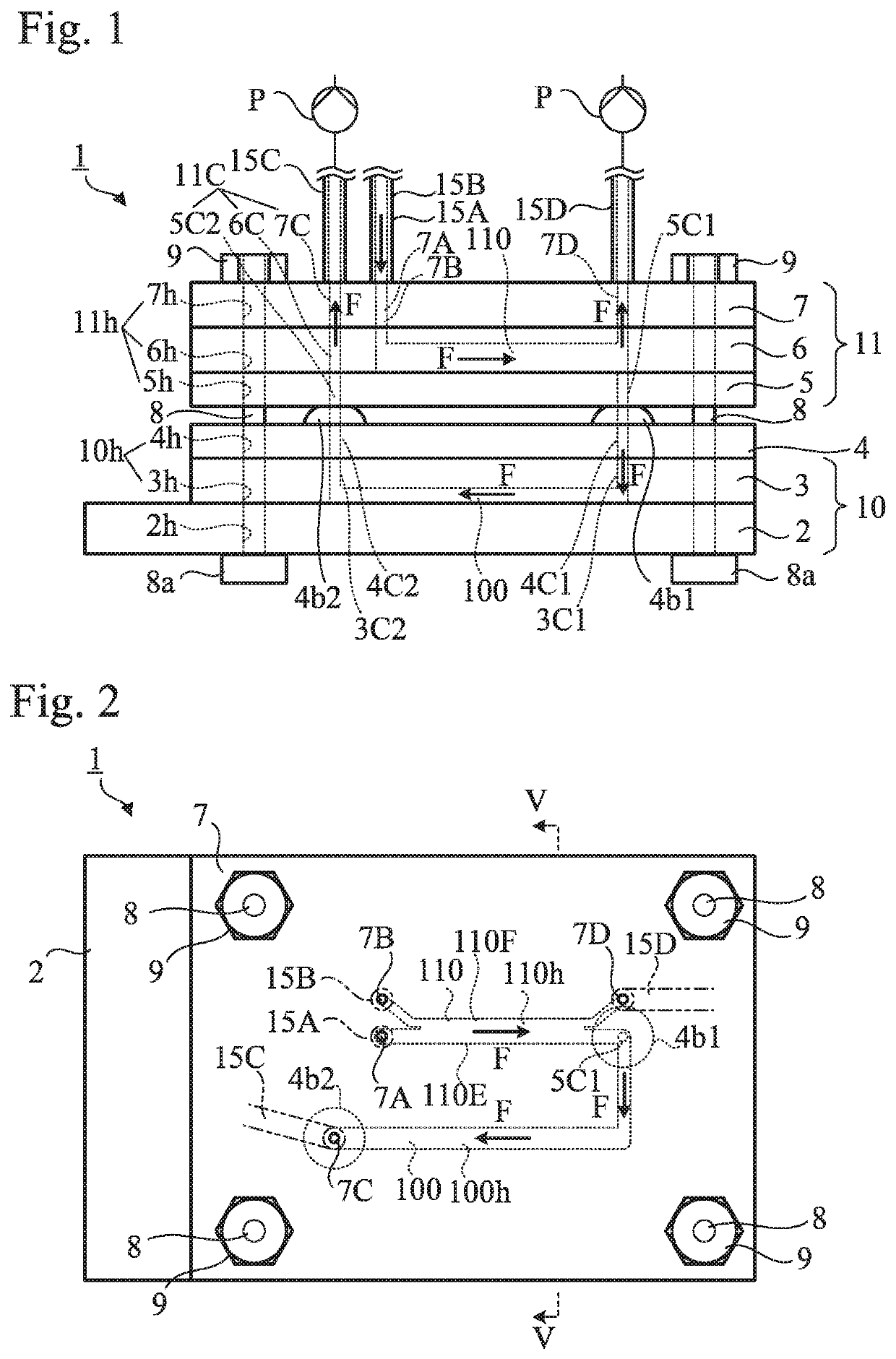
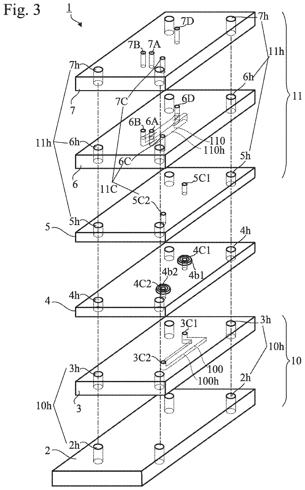
[0045]As shown in FIGS. 1 and 3, the cell capture apparatus 1 according to the embodiment includes a laminated structure including multiple plates stacked one on top of another, more specifically, a cell-capture lower flat plate 2, a cell-capture flow passage plate 3, a connection flat plate 4, a cell-separation lower flat plate 5, a cell-separation flow passage plate 6, and a cell-separation upper flat plate 7.

[0046]At four corners of the cell-capture lower flat plate 2, fixing through-holes 2h are formed. At four corners of the cell-capture flow passage plate 3, fixing through-holes 3h are formed. At four corners of the connection flat plate 4, fixing through-holes 4h are formed. At four...


PUM


Abstract

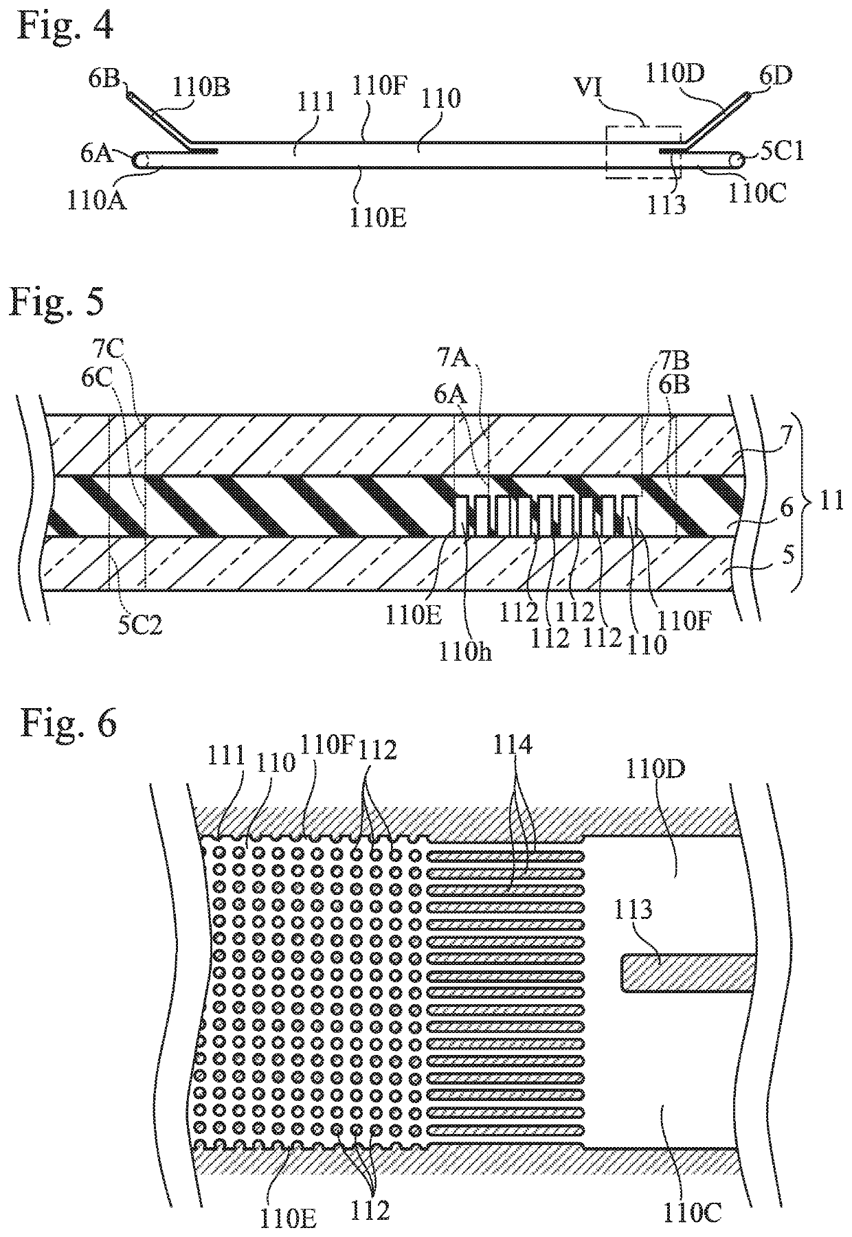
A cell capture apparatus includes a cell separation unit having a flat plate shape and a cell capture unit having a flat plate shape located therebelow. A liquid sample and a carrier liquid flow in a cell-separation flow passage of the cell separation unit. The liquid sample contains multiple large cells, multiple small cells, and a sample liquid component. The cell-separation flow passage separates a set of large cells and the carrier liquid from a set of small cells and the sample liquid component. The cell capture unit includes a large-cell flow passage in which the set of large cells and the carrier liquid flows, and multiple electrode wires for attracting the large cells by means of dielectrophoresis. Multiple cell capturing wells are formed in the large-cell flow passage. Each of the multiple cell capturing wells has a size that can capture one of the large cells attracted by the electrode wires.

Description

TECHNICAL FIELDField of the Invention[0001]The present invention relates to cell capture apparatuses that selectively isolate particular cells in a liquid sample and trap the particular cells for analysis.Background Art[0002]The blood of cancer patients contains circulating tumor cells (CTCs) that have broken away from the original cancer tissue. CTCs are considered to be relevant to the metastasis of cancer, and thus, it is anticipated that analysis of CTCs in blood will facilitate early detection of cancer and prognosis of metastasis. However, only very small amounts of CTCs can be found, i.e., only a few CTCs are contained in one billion cells of a cancer patient, which makes analysis extremely difficult. On the other hand, it is considered that individual CTCs have different characteristics, and it is desirable to analyze every single CTC.[0003]Apparatuses for analyzing cells have been proposed in which multiple target cells in liquid are attracted by means of dielectrophoresis ...

Claims


Application Information

Patent Timeline
IPC IPC(8): C12M1/00B01L3/00
CPCB01L3/502753B01L2300/123B01L2300/0883B01L2300/0809B01L2300/041B01L2300/168B01L2400/0424B01L3/50273B01L2300/06C12M47/04B01L3/502761B01L2200/0647B01L2300/0645C12M1/26C12M3/08B01L2300/0874B01L2200/0668B01L2200/0652B01L2400/086B01L2300/0887
Inventor KOMORI, TAKAYUKIKIM, SOOHYEONFUJII, TERUO
Owner NOK CORP
Learn More