
Valve, Hydraulic System and Motor Vehicle Gearbox

a hydraulic system and valve body technology, applied in the field of valves, can solve the problems of reducing the energy efficiency of the hydraulic system for the open-loop control of the actuator, and achieve the effect of reducing the energy efficiency of the hydraulic system

Active Publication Date: 2020-08-27
ZF FRIEDRICHSHAFEN AG
View PDF0 Cites 1 Cited by
  • Summary
  • Abstract
  • Description
  • Claims
  • Application Information

AI Technical Summary

Benefits of technology

This patent describes a valve that can safely shut off an actuator without needing to be powered. This is accomplished by using a hydraulic shut-off, which reduces energy efficiency in the hydraulic system. The valve includes a valve pocket that is always connected to a port, allowing for a fluidic connection that always exists, regardless of the position of the piston. This simplifies the mechanical configuration of the valve and facilitates the hydraulic open-loop control of the actuator, without the need for a hydraulic detent. Additionally, the valve allows for a force-free condition of the actuator during changeovers, reducing pressure peaks. The valve also includes a switchable shut-off valve that can be used to switch into a different condition without needing to actuate the actuator into that condition. Overall, this patent provides a solution for safely controlling the actuator in a hydraulic system without sacrificing energy efficiency.

Problems solved by technology

The application of energy in order to achieve such a condition reduces the energy efficiency of the hydraulic system for the open-loop control of the actuator, however.

Method used


Image

  • Valve, Hydraulic System and Motor Vehicle Gearbox
  • Valve, Hydraulic System and Motor Vehicle Gearbox
  • Valve, Hydraulic System and Motor Vehicle Gearbox

Examples


Embodiment Construction

[0030]Reference will now be made to embodiments of the invention, one or more examples of which are shown in the drawings. Each embodiment is provided by way of explanation of the invention, and not as a limitation of the invention. For example, features illustrated or described as part of one embodiment can be combined with another embodiment to yield still another embodiment. It is intended that the present invention include these and other modifications and variations to the embodiments described herein.

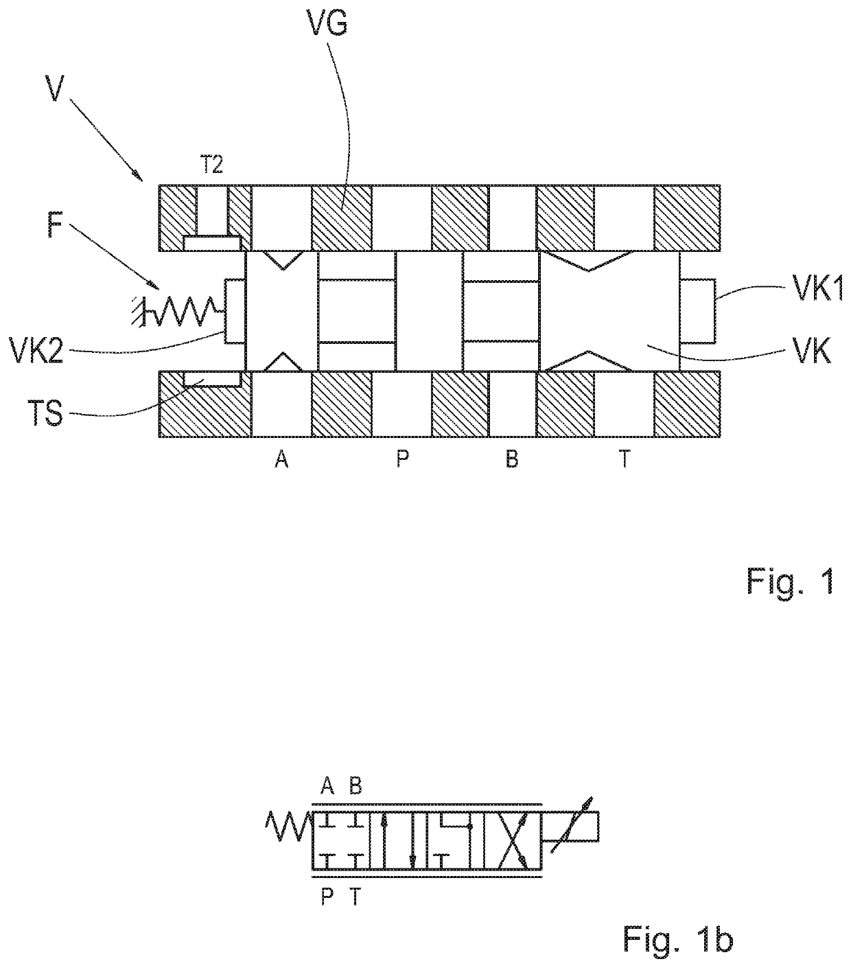
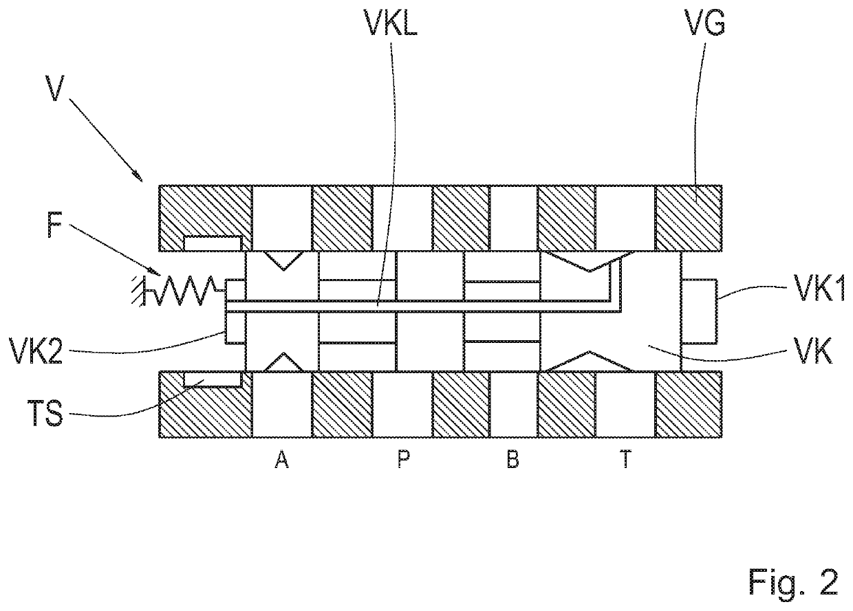
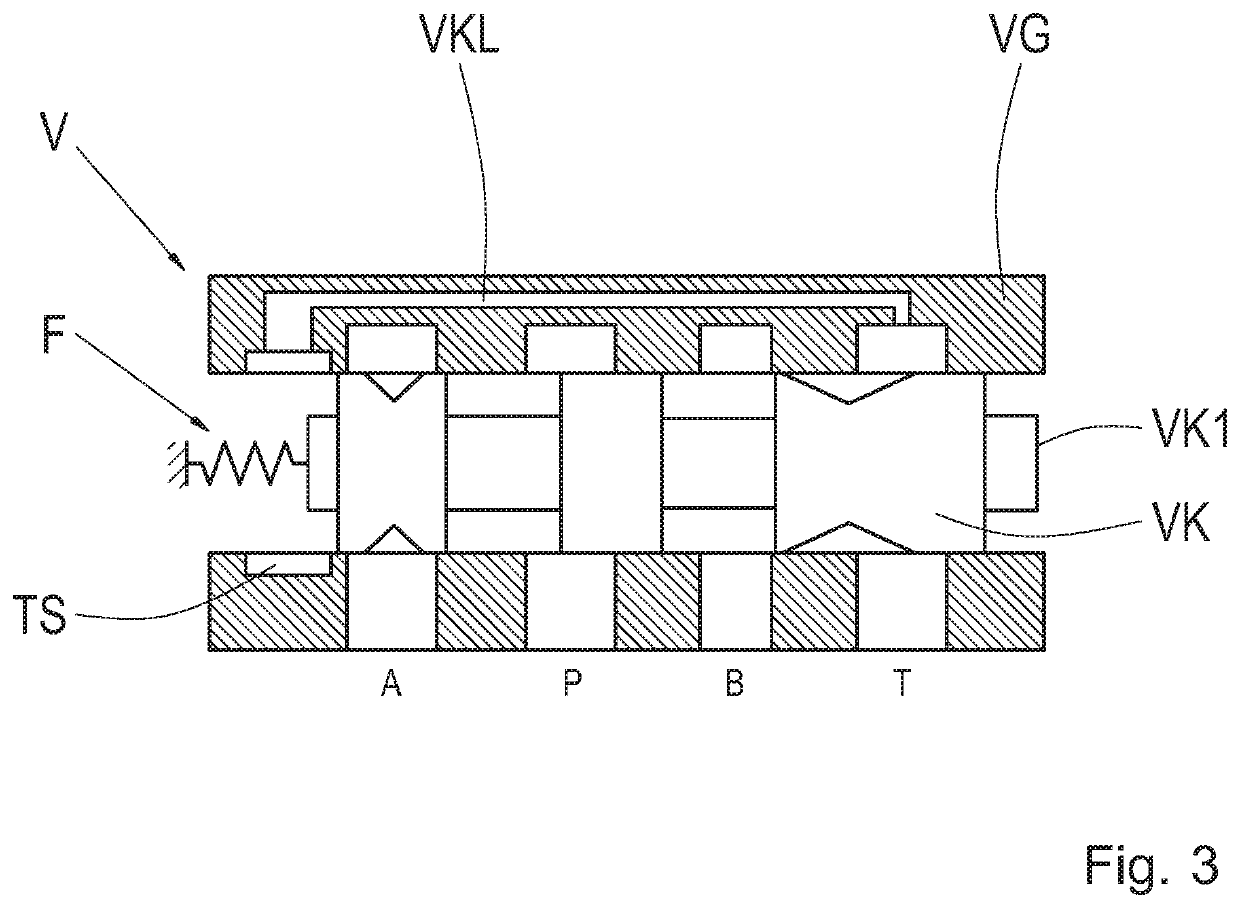
[0031]FIG. 1 shows a valve V according to a first exemplary embodiment of the invention. The valve V includes a housing VG and a piston VK guided therein. A first end VK1 of the piston VK can be acted upon by a force, for example, via application of a hydraulic or pneumatic pressure. Alternatively, a solenoid can act at the first end VK1, with the aid of which the piston VK is displaceable. The force acting upon the first end VK1 counteracts the force of a spring F, which acts upo...


PUM


Abstract

A valve (V, V1, V2) includes a housing (VG) and a piston (VK) displaceably guided therein. A first end (VK1) of the piston (VK) can be acted upon by a force, with the aid of which the piston (VK) is displaceable against a spring (F) acting upon a second end (VK2) of the piston (VK). The valve (V, V1, V2) has four switching conditions, in which four ports (A, B, P, T) in the housing (VG) are selectively connectable to one another or blocked with respect to one another. In a first switching condition, none of the ports (A, B, P, T) are connected to one another. The spring (F) is configured in such that, in the absence of an application of force onto the first end (VK1), the piston (VK) is held in a position, which corresponds to the first switching condition of the valve (V, V1, V2).

Description

CROSS-REFERENCE TO RELATED APPLICATIONS[0001]The present application is related and has right of priority to German Patent Application No. 10 2017 219 645.9 filed on Nov. 6, 2017 and to PCT International Publication No. WO2019 / 086424, both of which are incorporated by reference in their entirety for all purposes.FIELD OF THE INVENTION[0002]The invention relates generally to a valve, in particular a 4 / 4 directional valve. The invention further relates generally to a hydraulic system including such a valve, and to a motor vehicle transmission including this type of hydraulic system. The valve is not limited to the application in a hydraulic system, but rather can also be utilized in a pneumatic system.BACKGROUND[0003]Patent application DE 10 2007 033 690 A1 describes a hydraulic system for the open-loop control of a dual clutch transmission. Four double pistons, which are controlled by an open-loop system via a shift valve and two shift control valves, are utilized for shifting the ge...

Claims


Application Information

Patent Timeline
Patent Type & Authority Applications(United States)
IPC IPC(8): F16K11/07F16H61/02F15B13/04F16H61/30
CPCF16K11/07F16H61/0251F16K11/0716F16H61/30F15B13/0402F15B2211/3122F15B20/008F15B2211/3127F15B2211/322F15B2211/8636F15B2211/8752
Inventor KUDERMANN, KARSTENNOVAK, RAINERMOOSMANN, MARKUSPFLEGER, TOBIAS
Owner ZF FRIEDRICHSHAFEN AG
Learn More