
Aircraft environmental control and fuel tank inerting coupling system based on membrane separation method

a technology of aircraft environment control and fuel tank, which is applied in the direction of separation processes, energy-efficient board measures, transportation and packaging, etc., can solve the problems of aircraft fuel tank having a certain probability of combustion and explosion, complex structure and large, etc., and achieves simple system structure, high dehumidification efficiency, and reduced production costs

Active Publication Date: 2020-08-20
BEIHANG UNIV
View PDF0 Cites 3 Cited by
  • Summary
  • Abstract
  • Description
  • Claims
  • Application Information

AI Technical Summary

Benefits of technology

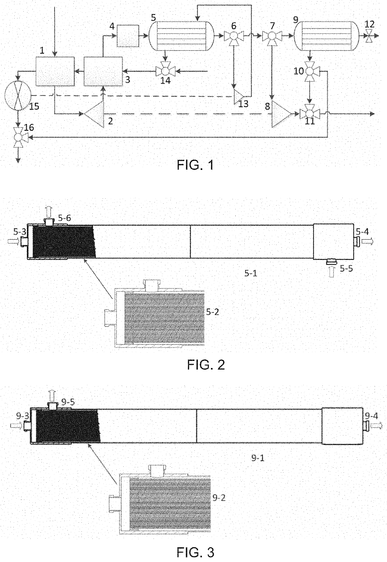
The patent proposes a coupling system where an aircraft environmental control system and a fuel tank inerting system are combined using membrane separation technology. The coupling system reduces the weight of the two independent systems and improves their performance by sharing temperature and pressure regulation and filtering components. The system also produces oxygen enriched air which can improve the oxygen content of the cabin air and the comfort of the aircraft crews and passengers. The additional efficient filtering system improves the quality of air supply in the cockpit and cabin of the aircraft, contributing to the aircraft development trend of safety, efficiency, and health.

Problems solved by technology

When the aircraft works in a high humidity condition water vapor will have an adverse impact on the aircraft environmental control system, so air dehumidification is required in the aircraft environmental control system.
It has the advantages of high water removal efficiency, large refrigeration capacity, but it has many components, leading to complex structure and large weight
In flight, the fuel tank of an aircraft has a certain probability of combustion and explosion.

Method used


Image

  • Aircraft environmental control and fuel tank inerting coupling system based on membrane separation method

Examples


Embodiment Construction

[0005]The dehumidification membrane in the dehumidification system and the oxygen nitrogen separation membrane in the oxygen nitrogen separation system have similar requirements for inlet air temperature, pressure, pollutant particles size and oil content. The air dehumidified by the dehumidification membrane has lower moisture content, which is helpful to improve the efficiency of the oxygen nitrogen separation membrane. Therefore, it is feasible and advanced to couple the membrane dehumidification aircraft environmental control system with the membrane separation fuel tank inerting system. In addition, the oxygen enriched air produced by the oxygen nitrogen separation membrane can be mixed with the air supply of the cabin, which can clearly improve the oxygen content of the cabin air and improve the comfort of the aircraft crews and passengers. The coupling system can share the temperature and pressure regulation and filtering devices, reduce the total weight of the two independen...


PUM

PropertyMeasurementUnit
temperatureaaaaaaaaaa
pressureaaaaaaaaaa
humidityaaaaaaaaaa

Abstract

Disclosed is an aircraft environmental control and fuel tank inerting coupling system based on a membrane separation method. The dehumidification of gas in an aircraft environmental control system and the separation of oxygen and nitrogen in a fuel tank inerting system are realized respectively, based on the selective permeability of a membrane to water vapour / air and oxygen / nitrogen. In the coupling system, part of drying gas passing through a membrane dehumidification heat exchanger (5) enters a membrane air separator (9), and the other part thereof is cooled through a large expansion turbine (8) and then directed into a cockpit for refrigeration; and nitrogen-rich gas generated by the membrane air separator (9) is directed into a fuel tank for inerting. Oxygen-rich gas is mixed with gas supplied by the environmental control system, thus increasing the oxygen content of gas supplied by the aircraft cockpit.

Description

TECHNICAL FIELD[0001]The present invention relates to a coupling system for aircraft environment control and fuel tank inerting based on the membrane separation is provided.BACKGROUND OF THE INVENTION[0002]When the aircraft works in a high humidity condition water vapor will have an adverse impact on the aircraft environmental control system, so air dehumidification is required in the aircraft environmental control system. At present, all the advanced aircrafts in the world adopt the high-pressure water removal environment control system. It has the advantages of high water removal efficiency, large refrigeration capacity, but it has many components, leading to complex structure and large weight[0003]High pressure air membrane dehumidification technology relies on the pressure difference of water vapor on both sides of the membrane to drive the water vapor diffusion across the membrane. Therefore, in the process of dehumidification, there is no need for condensation and heat release...

Claims


Application Information

Patent Timeline
Patent Type & Authority Applications(United States)
IPC IPC(8): B01D53/22B64D13/06B64D37/32B01D53/26
CPCB64D13/06B64D2013/0618B01D53/268B01D53/226B64D2013/0662B64D2013/0681B64D37/32B64D2013/0651B01D2053/224B01D46/00B01D2257/80B01D2259/4566B01D2256/10B01D2257/104B01D2259/4575B64D2013/0677Y02T50/40Y02T50/50
Inventor YUAN, WEIXINGZHENG, YANYU, BIN
Owner BEIHANG UNIV
Learn More