Laser clad layer forming method and laser cladding device
- Summary
- Abstract
- Description
- Claims
- Application Information
AI Technical Summary
Benefits of technology
Problems solved by technology
Method used
Image
Examples
first embodiment
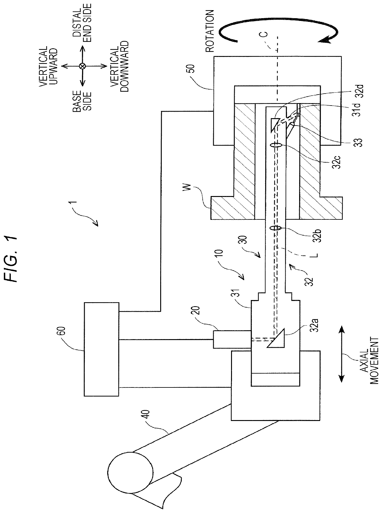
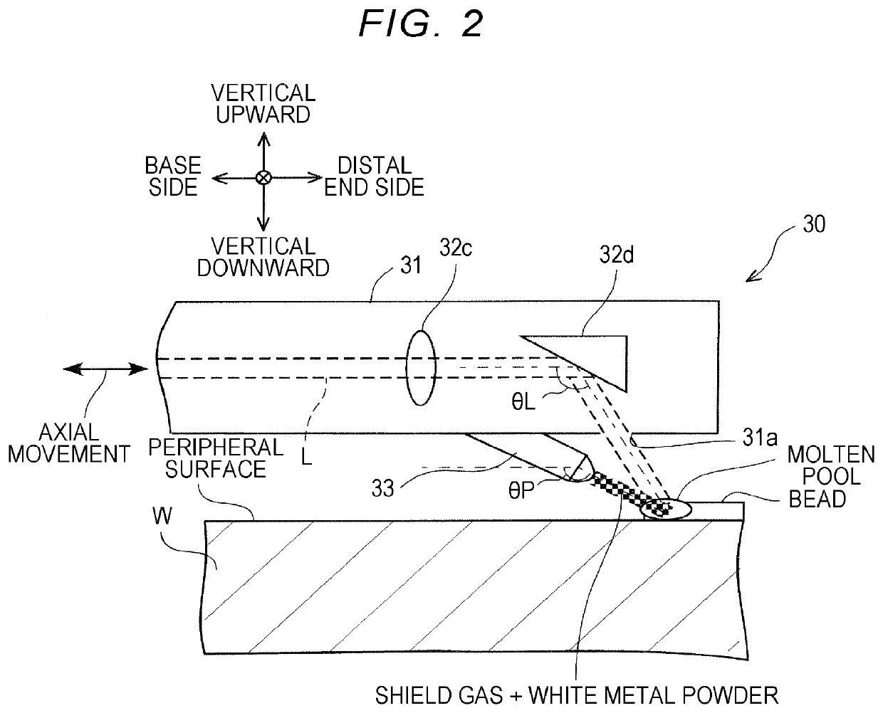
[0061]A modified example of the first embodiment will be described below with reference to FIG. 5. FIG. 5 is a perspective view schematically illustrating an example in which beads are formed on an inner peripheral surface of a workpiece W according to the modified example. In the above-mentioned embodiment, an inner peripheral surface of a workpiece W is partitioned into a plurality of areas in the circumferential direction such that each of the plurality of areas corresponds to a bead width, and a bead is formed in an axially straight shape in each area. However, in this modified example, an inner peripheral surface of a workpiece W is partitioned into a plurality of areas with a predetermined angle in the circumferential direction and a bead is formed in a rectangular wave shape by repeating rotation of the laser torch 30 in the circumferential direction and movement thereof in the axial direction in each area. Arrangement of the laser torch 30 relative to the workpiece W is the ...
third embodiment
[0107]In this embodiment, the workpiece W is a cylindrical or columnar member, a formation-scheduled portion for a laser clad layer is set on the outer peripheral surface thereof, and the forming process S3 is performed in a state in which the workpiece W is held such that the axial direction thereof is horizontal and the phase of the workpiece W is determined such that the forming-scheduled position of the bead is located on the uppermost side in the vertical direction on the outer peripheral surface. The same advantages as in the third embodiment are achieved in this embodiment. That is, by disposing the laser torch 30 above the outer peripheral surface of the workpiece W in the vertical direction and forming the bead while controlling the size of a molten pool which is formed due to irradiation with a laser beam, it is possible to continuously form a laser clad layer while preventing sagging of the bead.
[0108]A fifth embodiment of the disclosure will be described below with refer...
fifth embodiment
[0115]In the fifth embodiment, a reheating process of reheating the workpiece W using the temperature-controlled housing 70 may be provided after the forming process S13 has been performed. According to this modified example, since the bead is slowly cooled over time in the reheating process, it is possible to form a laser clad layer with more uniform and higher quality.
[0116]In the third embodiment, the bead is formed in a spiral shape on the inner peripheral surface of the workpiece W, but the disclosure is not limited thereto. For example, in the forming process S3, a process of holding the workpiece W such that the axial direction thereof is horizontal, irradiating a powder of a white metal with a laser beam while rotating the workpiece W such that the direction of the normal to the forming-scheduled position for the bead on the inner peripheral surface of the workpiece W is the vertical upward direction and supplying the powder, and melting the powder to form the bead in an ann...
PUM
| Property | Measurement | Unit |
|---|---|---|
| Temperature | aaaaa | aaaaa |
| Angle | aaaaa | aaaaa |
| Angle | aaaaa | aaaaa |
Abstract
Description
Claims
Application Information
 - R&D
- Intellectual Property
- Life Sciences
- Materials
- Tech Scout
- Unparalleled Data Quality
- Higher Quality Content
- 60% Fewer Hallucinations
Browse by: Latest US Patents, China's latest patents, Technical Efficacy Thesaurus, Application Domain, Technology Topic, Popular Technical Reports.
© 2025 PatSnap. All rights reserved.Legal|Privacy policy|Modern Slavery Act Transparency Statement|Sitemap|About US| Contact US: help@patsnap.com


