Dynamic Deployment of Network Applications Having Performance and Reliability Guarantees in Large Computing Networks

a network application and network technology, applied in the field of dynamic deployment of network applications having performance and reliability guarantees in large computing networks, can solve the problems of network, low control of network operators, and among the most complex industrial systems to be found anywhere in the world today, and achieve the effect of reducing time delays in data transmission

Active Publication Date: 2020-07-23
RISE RES INST OF SWEDEN AB
View PDF0 Cites 22 Cited by
  • Summary
  • Abstract
  • Description
  • Claims
  • Application Information

AI Technical Summary

Benefits of technology

The invention is a system for scheduling electronic data transmissions in a computer network. It includes an electronic reliability checker that examines the network topology and determines the reliability of data transmission routes between computerized nodes. It also includes an electronic bandwidth checker that calculates bandwidth allocations for the network. An electronic resource planner uses these reliability and bandwidth calculations to develop a computer-implementable deployment strategy that optimizes reliability, bandwidth, and end-to-end delay. The system can automatically monitor and decide-making for dynamically triggering recalculations of the scheduling based on changes in the networking conditions. Overall, the invention provides a more efficient and reliable way to schedule electronic data transmissions in computer networks.

Problems solved by technology

Large communication networks, such as T-Mobile's North American network or Microsoft's cloud network, are among the most complex industrial systems to be found anywhere in the world today.
However, the control plane technology provides some challenges as well, such as scalability issues and low control of the network operator on the paths used by the traffic in end-to-end services with consequent lack of resource optimization.
While these efforts in the prior art have been helpful, they have not yet provided an optimal solution for the problems they attempt to solve.
However, the solutions available in the prior art only focus on placing controllers whereas the consequent control traffic is often ignored, leading to numerous drawbacks.
In particular, flow delay is of growing importance as more services (e.g., Intelligent Transportation Systems (“ITS”)) require short response times for close to real-time applications.
Accordingly, the way cloud computing tasks have been planned and deployed will impact service performance with respect to how quickly and accurately a cloud computing result can be delivered (some results could get lost due to, e.g., link loss).

Method used


Image

  • Dynamic Deployment of Network Applications Having Performance and Reliability Guarantees in Large Computing Networks
  • Dynamic Deployment of Network Applications Having Performance and Reliability Guarantees in Large Computing Networks
  • Dynamic Deployment of Network Applications Having Performance and Reliability Guarantees in Large Computing Networks

Examples


example # 2

Example #2: Deployment of VMs for a Cloud Computing Task

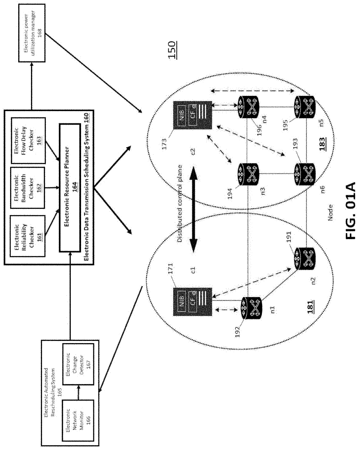
[0200]Deploying and executing a computational task in a distributed big data framework and architecture (e.g., Apache Spark or similar), is essentially identical to deploying a distributed control plane. Such an architecture generally allows for distributing a computation task within or across geo-distributed data centers. Within the context of a cloud computing application of a distributed cloud computing architecture, a manager entity, such a computerized management function within data transmission node 171 shown in FIG. 01A carries out computational tasks by controlling one or many computerized worker entities. Each computerized worker entity (e.g., switches 192) may host one or several computerized distributed agents which each may handle one or several computation tasks.

[0201]In this context, the electronic data transmission scheduling system 160 may map the deployment of a distributed computational infrastructure (or app...

application example # 3

Application Example #3: Deployment of a VNF Service Chain

[0204]Embodiments of the invention may be used to deploy service chains comprising a series of connected VNF instances. In this case, embodiments of the invention, namely the electronic data transmission scheduling system 160, essentially deploy computerized processing entities (e.g., data transmission nodes 171) (corresponding to the VNFs) without associating any electronic aggregator nodes—consequently, the reliability requirement becomes irrelevant.

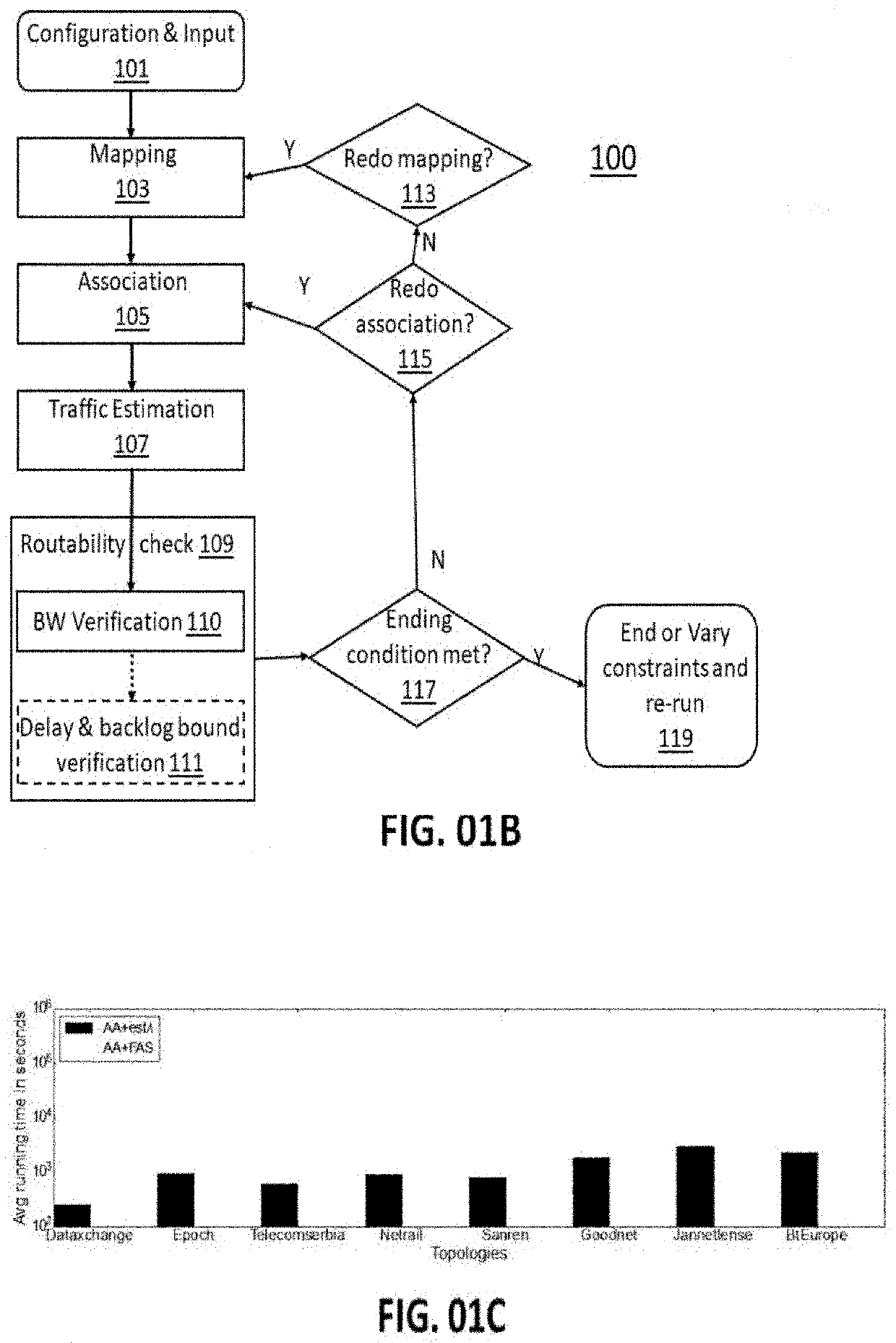
[0205]Hence, computerized processing associated with this embodiment of the invention is simplified to placement of a given number of VNFs on a network topology while accounting only for bandwidth and flow delay requirements. In practice this is achieved by setting the reliability R(G, j, C)=1) and assuming N∈Ø. To solve the deployment problem, a computerized system executes the steps from Workflow 100 shown in FIG. 01B, except for the “Association” step (step 105 shown in FIG. 0...


PUM


Abstract

Embodiments of the invention relate to computerized systems and computerized methods configured to optimize data transmission paths in a large-scale computerized network relative to reliability and bandwidth requirements. Embodiments of the invention further relate to computerized systems and methods that direct and control the physical adjustments to data transmission paths in a large-scale network's composition of computerized data transmission nodes in order to limit data end-to-end transmission delay in a computerized network to a delay within a calculated worst-case delay bound.

Description

FIELD[0001]Embodiments of the invention relate to computerized systems and computerized methods configured to optimize data transmission paths in a large-scale computerized network relative to reliability and bandwidth requirements. Embodiments of the invention further relate to computerized systems and methods that direct and control physical adjustments to data transmission paths in a large-scale network's composition of computerized data transmission nodes in order to limit data end-to-end transmission delay in a computerized network to a delay within a calculated worst-case delay bound.BACKGROUND[0002]The following description includes information that may be useful in understanding embodiments of the invention. It is not an admission that any of the information provided herein is prior art or relevant to the presently claimed invention, or that any publication specifically or implicitly referenced is prior art.[0003]Large communication networks, such as T-Mobile's North America...

Claims


Application Information

Patent Timeline
IPC IPC(8): H04L12/717H04L12/751H04L12/725H04L12/26H04L45/02H04L45/42H04L47/76
CPCH04L43/0852H04L45/42H04L45/02H04L43/0817H04L45/302H04L43/50H04L45/64H04L45/14H04L41/0836H04L41/0886H04L47/822H04L47/76H04L45/125H04L47/83
Inventor LIU, SHAOTENGSTEINERT, REBECCAKOSTIC, DEJAN
Owner RISE RES INST OF SWEDEN AB
Why Eureka
Try Eureka