
Enhanced operation of vehicle hazard and lighting communication systems

a technology of vehicle hazard and communication system, which is applied in the direction of vehicular safety arrangments, pedestrian/occupant safety arrangements, and emergency or hazard lights for automobiles, rvs, etc., can solve the problems of insufficient visibility, many citizens are killed each year, and do not provide a high level of clear visual communication to other drivers

Pending Publication Date: 2020-06-18
ESS HELP INC
View PDF2 Cites 14 Cited by
  • Summary
  • Abstract
  • Description
  • Claims
  • Application Information

AI Technical Summary

Benefits of technology

The present invention is well-suited to achieve its goals and objectives. Its design allows for easy implementation and modification as needed, which is important for those working in the field of medical devices. The technical effects of this invention include improved functionality, improved efficiency, and enhanced user experience. These benefits can be realized through various improvements such as advanced materials, innovative designs, and improved manufacturing processes.

Problems solved by technology

A problem with existing systems and modes of operation with respect to emergency flashers is that a double blinker flashing during an emergency, on a roadside for example, is insufficiently visible and does not provide a high level of clear visual communication to other drivers that a safety hazard exists.
Many citizens are killed each year while using their flashing hazard lights during emergency situations on the road.
Flashing or double blinking emergency lights are nowhere near as effective as strobing hazard lights.
Another problem with existing emergency flashers is that they are not always deployed when a genuine emergency exists.
Occupants may be injured or otherwise unable to deploy the emergency flashers when they are needed most.
A disabled vehicle on a roadway is a hazard to other vehicles and all vehicle occupants.
Nevertheless, hazard lights can be critical in quickly locating vehicles that have left the roadway either purposefully (e.g., to leave the flow of traffic) or as the result of an accident.

Method used


Image

  • Enhanced operation of vehicle hazard and lighting communication systems
  • Enhanced operation of vehicle hazard and lighting communication systems
  • Enhanced operation of vehicle hazard and lighting communication systems

Examples


Embodiment Construction

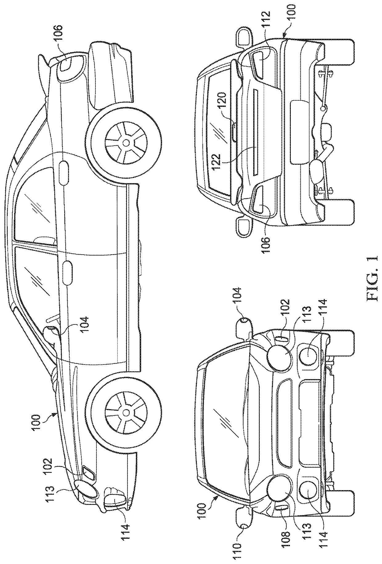
[0052]In various embodiments of the present disclosure, devices and systems are implemented that provide enhanced visual communication cues via existing or replacement signal and / or hazard lights on an automobile. Signal and hazard lights in most cars cycle between light and dark at a rate between once and twice per second or 1-2 Hz. Such a rate is believed to be adequate for signaling lane changes and other non-emergency situations. However, existing cars and hazard light flasher systems do not take into account the need for, and benefit of, communicating an emergency situation utilizing an enhanced flash rate. A vehicle traveling 70 miles per hour will travel over 50 feet before a 2 Hz cycle has completed one time. This distance can mean the difference between an accident and a close call. Further, reaction time and ability to maneuver or stop must be taken into account. The quicker a driver takes notice of a problem, the more likely he or she can still have time to avoid a seriou...


PUM


Abstract

A system includes a microcontroller that controls illumination of a plurality of vehicle lights that are operable in a flashing state wherein the plurality of lights operate as hazard flashers visible on a front and rear of a vehicle and a strobing state wherein the plurality of lights operate as strobing lights visible on the front and rear of the vehicle. The system includes a strobe activation switch that provides a signal to the microcontroller to operate the plurality of vehicle lights in the second strobing state. The microcontroller operates the plurality of vehicle lights in the first hazard flasher state in response activation of an existing hazard flasher switch. The strobing state has a flash rate that is perceptibly faster than a flash rate of the flashing state.

Description

CROSS-REFERENCE TO RELATED CASES[0001]This application claims the benefit of U.S. provisional patent application Ser. No. 62 / 778,151, filed on Dec. 11, 2018, and incorporates such provisional application by reference into this disclosure as if fully set out at this point.FIELD OF THE INVENTION[0002]The present disclosure relates to emergency or hazard lights for automobiles, RVs, trailers, motorcycles and vehicles in general, and, more particularly, to emergency or hazard lights that strobe and give visual direction for increased safety and visibility.BACKGROUND OF THE INVENTION[0003]The advent of light emitting diode (LED) technologies has enhanced lighting capabilities to a point where vehicle-based lights are becoming more effective as visual signals during emergencies and hazardous situations. Emergency services, law enforcement agencies, traffic control, and other government agencies have recognized this fact and added separate strobe lighting systems to their vehicles. These s...

Claims


Application Information

Patent Timeline
Patent Type & Authority Applications(United States)
IPC IPC(8): B60Q1/46B60Q1/34F21S41/60
CPCF21W2103/30B60Q1/346B60Q1/46F21S41/60B60Q1/52B60Q2900/40B60Q2900/10B60Q1/0094B60Q1/44B60Q3/00B60R21/01B60R21/0132F21V23/001B60Q2300/054B60Q1/30B60Y2200/11B60Y2200/147B60Y2200/12F21V23/0407B60R21/00
Inventor TUCKER, DAVID M.INCORVAIA, MIKEPOWERS, STEPHEN T.TUCKER, AUSTIN REECETUCKER, DANIEL ANTHONY
Owner ESS HELP INC
Learn More