3D graphene

Pending Publication Date: 2020-06-11
RD GROUPCO LTD
View PDF2 Cites 1 Cited by
  • Summary
  • Abstract
  • Description
  • Claims
  • Application Information

AI Technical Summary

Benefits of technology

The invention is about a method for creating 3D graphene structures on a surface of a substrate using a laser beam to convert a carbon source (such as a sheet) into a 3D graphene material. The method has several advantages: controllable formation and adherence to the substrate, accurate control of parameters, simple and fast with no need for vacuum conditions or complex equipment, and easy removal of unconverted carbon source without damaging the substrate. The absence of a fluid intermediate the carbon source and substrate may enhance the formation and adherence of the graphene.

Problems solved by technology

However, there are significant challenges in scaling up 2D graphene manufacturing processes which typically require exfoliation of graphite and transfer of exfoliated graphene sheets onto a substrate or complex deposition processes involving physical or chemical vapour deposition combined with post-deposition annealing treatments.
The practical applications of 3D graphene, however, are currently limited by difficulties in depositing 3D graphene structures in a controlled way onto substrates.
Such methods are slow and not suited for in-line processing as used, for example, in the manufacture of electronic device components.
It is also difficult to control the precise placement of the resultant 3D graphene structure on the substrate, making the production of nanoscale electronic devices problematic.

Method used


Image

  • 3D graphene
  • 3D graphene
  • 3D graphene

Examples


first example embodiment

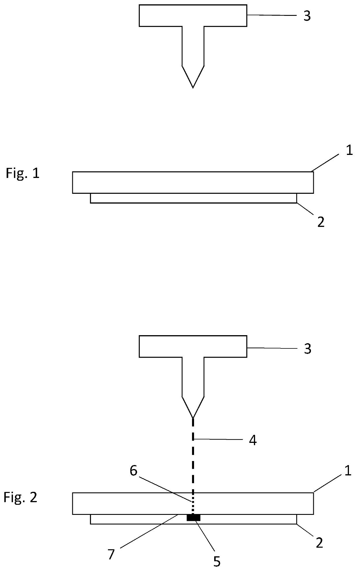
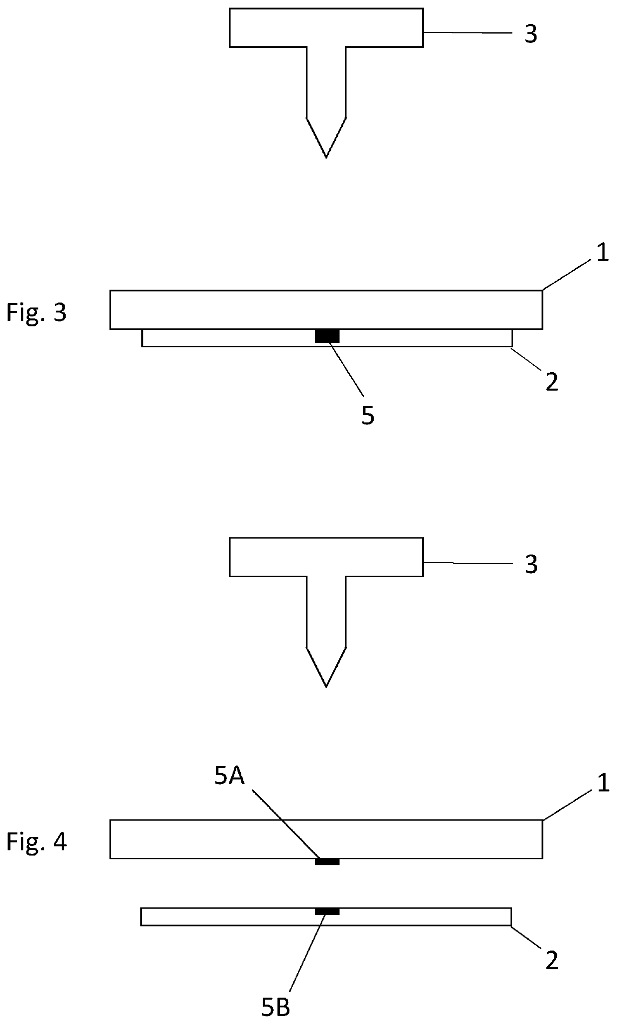
[0093]3D graphene was deposited on and adhered to a silicon substrate by the method set out below and as illustrated in FIGS. 1 to 4. A 600 μm thick silicon substrate 1 was placed directly on top of a 120 μm thick polyimide film, as shown in FIG. 1.

[0094]A CO2 infrared pulsed laser engraving and cutting system (the Trotec Speedy 400 flexx) 3 was used to direct a laser beam 4 at a surface of the substrate facing away from the polyimide film, as shown in FIG. 2. The laser system was tuned to emit light at a wavelength of 10.6 μm, with a beam size of 50 μm, a pulse duration of 14 μs and a power of 14.14 W. The laser beam was scanned across the surface of the substrate at a scan rate of 284 mm / s. The process was carried out at room temperature and at atmospheric pressure.

[0095]As shown in FIG. 2, a portion 5 of the polyimide film, immediately adjacent to the region of the substrate at which the laser beam was directed, was converted into 3D graphene. Without intending to be bound by the...

second example embodiment

[0104]3D graphene was deposited on and adhered to a polystyrene substrate by the method set out below and as illustrated in FIGS. 7 to 10. A 25 μm thick polyimide film 8 was placed directly on top of a 600 μm thick polystyrene substrate 9, as shown in FIG. 7.

[0105]A CO2 infrared pulsed laser engraving and cutting system (the Trotec Speedy 400 flexx) 10 was used to direct a laser beam 11 at a surface of the polyimide film 8 facing away from the substrate 9, as shown in FIG. 8. The laser system was tuned to emit light at a wavelength of 10.6 μm, with a beam size of 50 μm, a pulse duration of 14 μs and a power of 6 W. The laser beam was scanned across the surface of the substrate at a scan rate of 87.5 mm / s. The process was carried out at room temperature and at atmospheric pressure.

[0106]As shown in FIG. 8, a portion 12 of the polyimide film, at which the laser beam was directed, was converted into 3D graphene. The full thickness of the polyimide film was converted into 3D graphene.

[0...


PUM


Abstract

A method of forming a 3D graphene material adhered to a surface of a substrate comprises: providing a carbon source on the surface of the substrate; and exposing at least a portion of the carbon source and / or at least a portion of the substrate to a laser beam, thereby converting at least a portion of the carbon source into a 3D graphene material adhered to the surface of the substrate.

Description

FIELD OF THE INVENTION[0001]The invention relates to 3D graphene materials, methods of forming 3D graphene materials adhered to substrates, systems comprising 3D graphene materials adhered to substrates, device components comprising 3D graphene materials and methods of manufacturing device components comprising 3D graphene materials.BACKGROUND TO THE INVENTION[0002]Carbon is known to form many different allotropes. Allotropes such as diamond (in which a face-centred cubic lattice is decorated with a motif of two sp3-hybridised, tetrahedrally-arranged carbon atoms per primitive unit cell) or graphite (in which sp2-hybridised carbon atoms are arranged hexagonally to form planar sheets, adjacent sheets being held together by weak van der Waals interactions), have been known for a long time. Other carbon-based structures, such as graphenes, buckminsterfullerenes, carbon nanotubes, carbon nanoribbons, diamond-like carbons and amorphous carbons, have only recently been discovered.[0003]Gr...

Claims


Application Information

Patent Timeline
IPC IPC(8): C01B32/184
CPCC01P2004/30C01P2006/80B82Y30/00C01P2002/82C01B32/184B82Y40/00C01P2004/04C30B1/02C30B29/02
Inventor CAFFIO, MARCOMARQUORDT, CLAUS
Owner RD GROUPCO LTD
Why Eureka
Try Eureka