
Intelligent learning device for part state detection and identification

a learning device and intelligent technology, applied in the field of parts state prediction, can solve the problems of inability to predict the impact of wear on the underlying microstructure of the part, the material composition of the part is altered, and the parts are gradually worn ou

Active Publication Date: 2020-06-04
RAYTHEON TECH CORP
View PDF0 Cites 1 Cited by
  • Summary
  • Abstract
  • Description
  • Claims
  • Application Information

AI Technical Summary

Benefits of technology

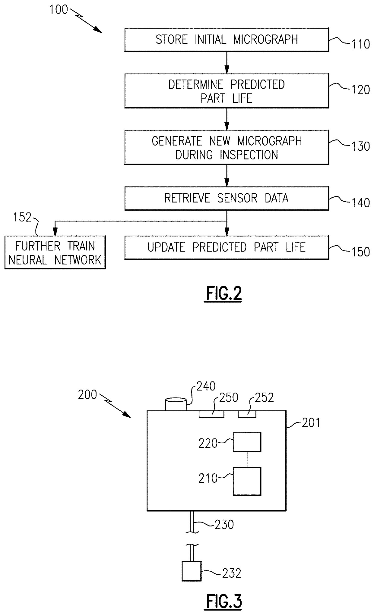
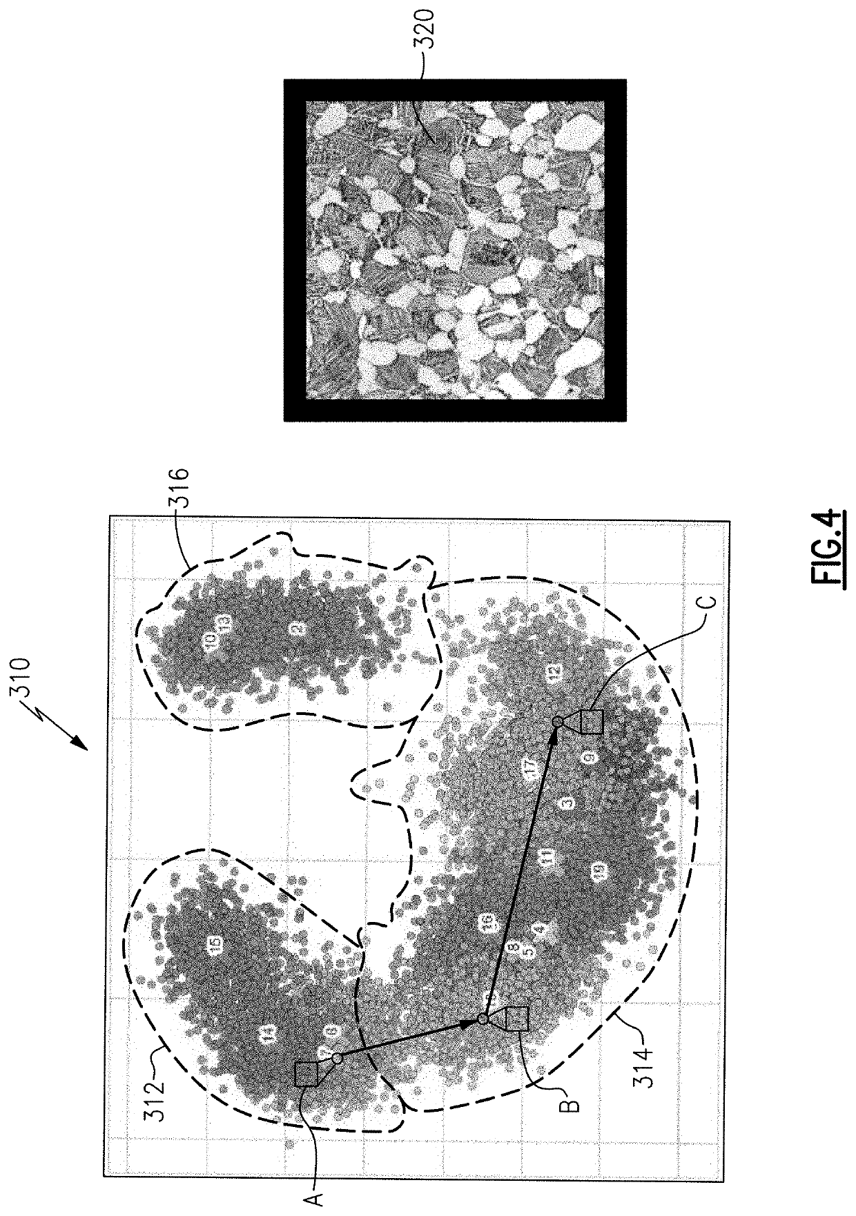
The patent describes a method for analyzing a part by providing an initial micrograph of the part to a trained model, receiving a data set representative of the parts' operating conditions, and outputting an expected state of the part based on the input data set and the initial micrograph. The expected state can include a simulated micrograph and expected parameters of the part. The training process involves generating artificial material samples based on authentic samples and updating or replacing them with subsequent authentic samples. The system can also include a tool for monitoring a part condition by providing the initial micrograph and data set to the trained model, and outputting the expected state of the part based on the input data set and the initial micrograph. The "technical effect" of the patent is that it provides a way to analyze and predict the performance of parts using advanced technology such as generative flow neural networks and physics-based models.

Problems solved by technology

The exposure to extreme stresses gradually wears the parts, and can in some examples alter the material composition of the parts.
Current models for determining the life of the part are incapable of predicting the impact that the wear has on the underlying microstructure of the part and are incapable of factoring non-engine parameters such operational environment, time between usage, storage conditions, and the like.

Method used


Image

  • Intelligent learning device for part state detection and identification
  • Intelligent learning device for part state detection and identification
  • Intelligent learning device for part state detection and identification

Examples


Embodiment Construction

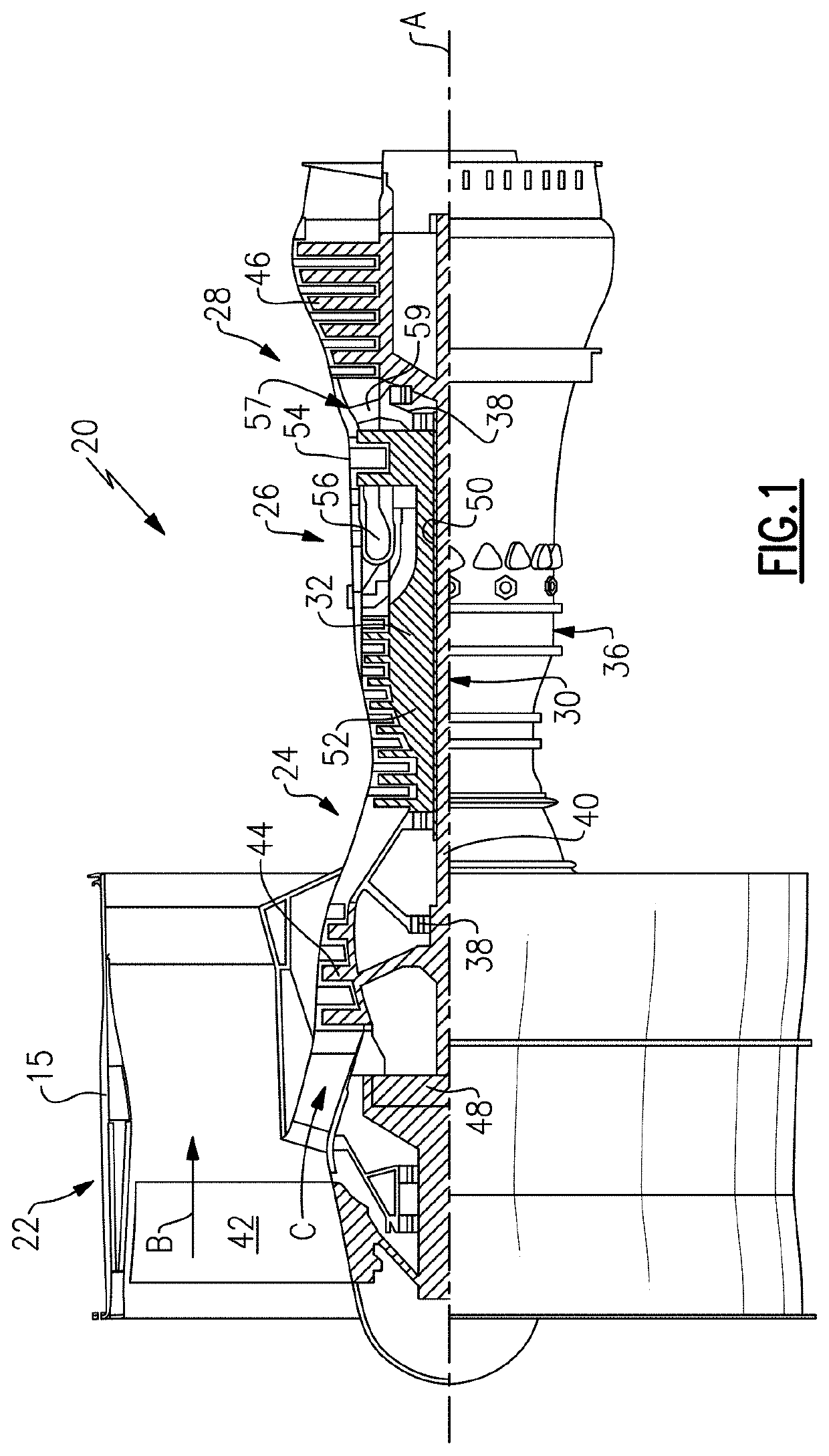
[0027]FIG. 1 schematically illustrates a gas turbine engine 20. The gas turbine engine 20 is disclosed herein as a two-spool turbofan that generally incorporates a fan section 22, a compressor section 24, a combustor section 26 and a turbine section 28. The fan section 22 drives air along a bypass flow path B in a bypass duct defined within a nacelle 15, and also drives air along a core flow path C for compression and communication into the combustor section 26 then expansion through the turbine section 28. Although depicted as a two-spool turbofan gas turbine engine in the disclosed non-limiting embodiment, it should be understood that the concepts described herein are not limited to use with two-spool turbofans as the teachings may be applied to other types of turbine engines including three-spool architectures.

[0028]The exemplary engine 20 generally includes a low speed spool 30 and a high speed spool 32 mounted for rotation about an engine central longitudinal axis A relative to...


PUM


Abstract

A tool for monitoring a part condition includes a computerized device having a processor and a memory. The computerized device includes at least one of a camera and an image input and a network connection configured to connect the computerized device to a data network. The memory stores instructions for causing the processor to perform the steps of providing an initial micrograph of a part to a trained model, providing a data set representative of operating conditions of the part to the trained model, and outputting an expected state of the part from the trained model based at least in part on the input data set and the initial micrograph.

Description

TECHNICAL FIELD[0001]The present disclosure relates generally to predicting a materials state of a part, and more specifically to making such a prediction with the assistance of a trained neural network.BACKGROUND[0002]Gas turbine engines, such as those utilized in commercial and military aircraft, include a compressor section that compresses air, a combustor section in which the compressed air is mixed with a fuel and ignited, and a turbine section across which the resultant combustion products are expanded. The expansion of the combustion products drives the turbine section to rotate. As the turbine section is connected to the compressor section via a shaft, the rotation of the turbine section further drives the compressor section to rotate. In some examples, a fan is also connected to the shaft and is driven to rotate via rotation of the turbine as well.[0003]Gas turbine engines include multiple engine components, each of which are exposed to extreme stresses during operation of ...

Claims


Application Information

Patent Timeline
IPC IPC(8): G01M15/14G06N3/08G06N3/04
CPCG01M15/14G06N3/04G06N3/08G06T7/0004G06T2207/20084G06T2207/30164
Inventor SOMANATH, NAGENDRAMERLI, ANYA B.NORAAS, RYAN B.GIERING, MICHAEL J.OSHIN, OLUSEGUN T.
Owner RAYTHEON TECH CORP
Learn More