
Real time markerless motion tracking using linked kinematic chains

a technology of linked kinematic chains and motion tracking, applied in the field of markers, can solve the problems of limited measuring range, high cost, low resolution,

Active Publication Date: 2007-08-14
NAT TECH & ENG SOLUTIONS OF SANDIA LLC
View PDF4 Cites 392 Cited by
  • Summary
  • Abstract
  • Description
  • Claims
  • Application Information

AI Technical Summary

Benefits of technology

[0046]Another object of this invention is to provide a method using volumetric 3D data for tracking purposes. The data is not actual range data due to sensor related drawbacks: high cost, low resolution, limited measuring range, safety concerns, and insufficient data acquisition speed. Instead 3D data is obtained through a triangulation based technique, which employs multiple (four in an example embodiment) cameras looking from different angles into the workspace to create a “visual hull” of any object within the workspace. Accordingly the problems of extrapolating a 3D pose from 2D information are avoided.
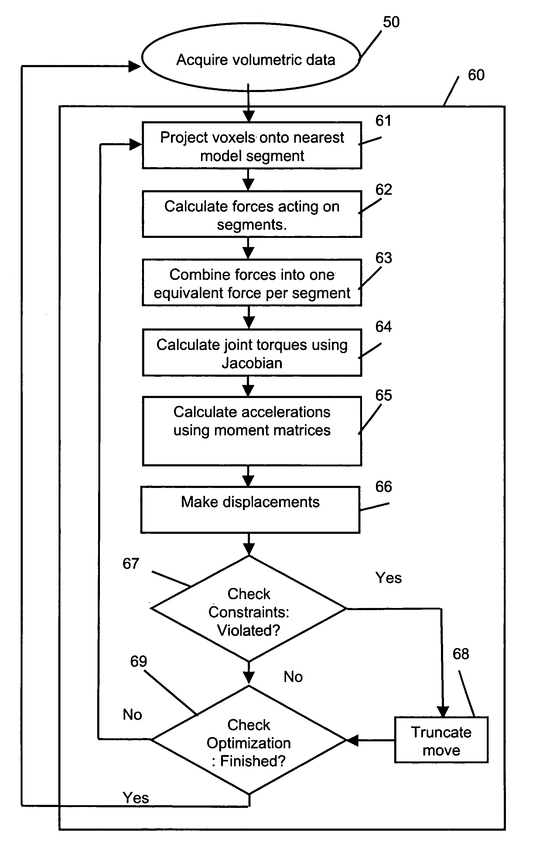
[0050]Another object of this invention is to provide a novel iterative optimization scheme to pull the model from alignment with the previous data set into alignment with the current data set. The process is efficient enough to operate in real-time, which means the adjustment between data sets should be very small, thereby allowing this method to work reliably.

Problems solved by technology

The data is not actual range data due to sensor related drawbacks: high cost, low resolution, limited measuring range, safety concerns, and insufficient data acquisition speed.

Method used


Image

  • Real time markerless motion tracking using linked kinematic chains
  • Real time markerless motion tracking using linked kinematic chains
  • Real time markerless motion tracking using linked kinematic chains

Examples


Embodiment Construction

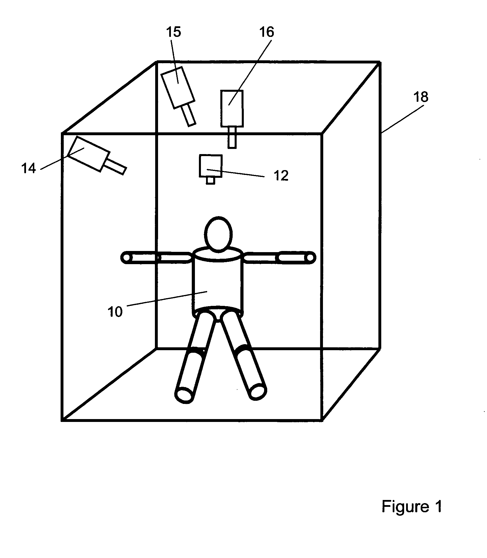
[0071]Video Imaging System: A video imaging system comprises a multiple of video cameras, frame grabber or data acquisition cards providing means for digitally capturing the camera images and a computer or similar means for digitally processing the images. As illustrated in FIG. 1, in an embodiment of the invention the method was applied to tracking a subject (10) within a thee dimensional workspace (18) using a video imaging system having a video camera (12) in the front of the workspace, two video cameras (14 and 15) located in corners of the workspace, and one video camera (16) located in the ceiling of workspace (16). In this embodiment of the method, color video cameras were used but monochrome cameras could be used as well, with some sacrifice in performance as will become apparent below. The video cameras in combination with four PCI-bus frame grabber cards (not shown) and a personal computer (not shown) comprise a video imaging system, commonly referred to as a Real-Time-Sha...


PUM


Abstract

A markerless method is described for tracking the motion of subjects in a three dimensional environment using a model based on linked kinematic chains. The invention is suitable for tracking robotic, animal or human subjects in real-time using a single computer with inexpensive video equipment, and does not require the use of markers or specialized clothing. A simple model of rigid linked segments is constructed of the subject and tracked using three dimensional volumetric data collected by a multiple camera video imaging system. A physics based method is then used to compute forces to align the model with subsequent volumetric data sets in real-time. The method is able to handle occlusion of segments and accommodates joint limits, velocity constraints, and collision constraints and provides for error recovery. The method further provides for elimination of singularities in Jacobian based calculations, which has been problematic in alternative methods.

Description

CROSS REFERENCE TO RELATED APPLICATIONS[0001]This application claims the benefit of U.S. Provisional Application No. 60 / 452,773 filed on Mar. 7, 2003.FEDERALLY SPONSORED RESEARCH[0002]The Government has rights in this invention pursuant to Department of Energy Contract No. DE-AC04-94AL85000 with Sandia Corporation.BACKGROUND OF THE INVENTION[0003]The present invention relates to markerless methods for tracking the motion of a subject within a 3-dimensional (3D) space. The subject can be a human form or any form that can be modeled by a structure comprised of rigid linked segments, referred to in the art as linked kinematic chains. Linked kinematic chains are representations of non-deformable segments of the form being tracked. For example; a model of a human form could comprise rigid geometric segments, ellipsoids and cylinders, representing the head, torso, and limbs, mechanically interconnected by flexible joints that provide for rotation and angular positioning between the segmen...

Claims


Application Information

Patent Timeline
IPC IPC(8): G06T17/10G06K9/32G06K9/64G06T7/20
CPCA61B5/1113A61B5/1114A61B5/1128G06K9/00369G06T7/2046A61B5/4528G06T2200/04G06T2207/30196G06T7/251G06V40/103
Inventor LUCK, JASON P.SMALL, DANIEL E.
Owner NAT TECH & ENG SOLUTIONS OF SANDIA LLC
Learn More