Combustion cleaning system and method

a combustion cleaning and combustion technology, applied in the direction of cleaning heat-transfer devices, cleaning processes and apparatuses, lighting and heating apparatuses, etc., can solve the problems of slagging and fouling of downstream heat transfer surfaces, restricting and redirecting flow patterns, and heat recovery steam generators (hrsg)

Active Publication Date: 2020-06-04
BARRETO VINCENT P
View PDF4 Cites 0 Cited by
  • Summary
  • Abstract
  • Description
  • Claims
  • Application Information

AI Technical Summary

Benefits of technology

The present invention is a mobile combustion cleaning system for removing debris from heat exchange surfaces. The system includes a mobile cart with a controller and a power supply, which mix and combust fuel and air using a shaped impulse wave to remove debris. The system also has a navigation controller for moving the distribution network around the heat exchange surfaces and an outlet for transmitting the impulse wave onto the surfaces to remove debris. The method involves analyzing the area surrounding the heat exchange surfaces, mapping a route for moving the distribution network, configuring the network, generating an impulse wave, measuring pressure, moving to the next location, and repeating the process until pressure is acceptable. The technical effect of the invention is a more efficient and effective cleaning of heat exchange surfaces, reducing downtime for maintenance.

Problems solved by technology

Burning of hydrocarbon fuels to produce high pressure steam can result in slagging and fouling of downstream heat transfer surfaces due to the bi-products of the combustion process.
Heat recovery steam generators (HRSG) in gas fired combined cycle plants thought to burn “clean” that do not employ an on-line cleaning system can also foul due to excessive corrosion, sulfide salts and other constituents that may precipitate out of the process gas stream.
As the heat transfer surfaces continue to foul, the mass loading of the deposits can also restrict and redirect flow patterns.
As a result, buildups of soot, ash, slag, or iron oxide mill scale on various surfaces and / or structures which can become fouled and inhibit the transfer of heat and therefore decrease the efficiency of the system.
In addition, these solutions can also be expensive to operate and cause erosion or destruction to the heat transfer surfaces.
Because of the potential destruction caused by some of these solutions, their use is restricted and infrequent.
Infrequent and ineffective operation of the cleaning devices or non-existent cleaning devices can result in fouling of the on-line cleaning devices, or the heat recovery steam generators (HRSG), adding to maintenance costs and leading to unplanned outages.
In addition, offline forms of cleaning such as high pressure water washing, which generates a large amount of hazardous waste water and dry ice blasting which is slow and cumbersome, are unable to reach deep into the tube bundles and provide minimal operational improvement while indiscriminate blasting created by repeatedly inserting and igniting bags inflated with a combustible mixture of gas and pure oxygen provide high intensity detonations that expose the entire structure to potentially damaging pressure waves while adding highly elevated safety concerns for personnel.
There have, of course, been many attempts to solve the inherent problems associated with industrial cleaning systems, however, many suffer from the same difficulties as previously mentioned.

Method used


Image

  • Combustion cleaning system and method
  • Combustion cleaning system and method
  • Combustion cleaning system and method

Examples


Embodiment Construction

[0018]As required, detailed embodiments of the present invention are disclosed herein; however, it is to be understood that the disclosed embodiments are merely exemplary of the invention, which may be embodied in various forms. Therefore, specific structural and functional details disclosed herein are not to be interpreted as limiting, but merely as a basis for the claims and as a representative basis for teaching one skilled in the art to variously employ the present invention in virtually any appropriately detailed structure.

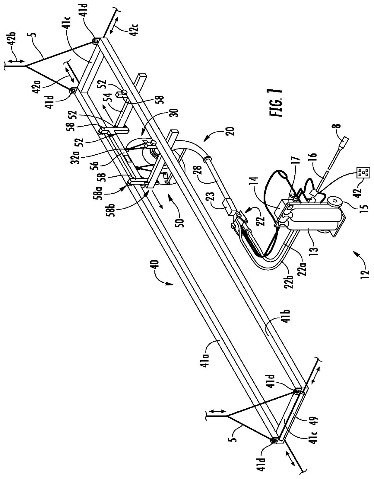
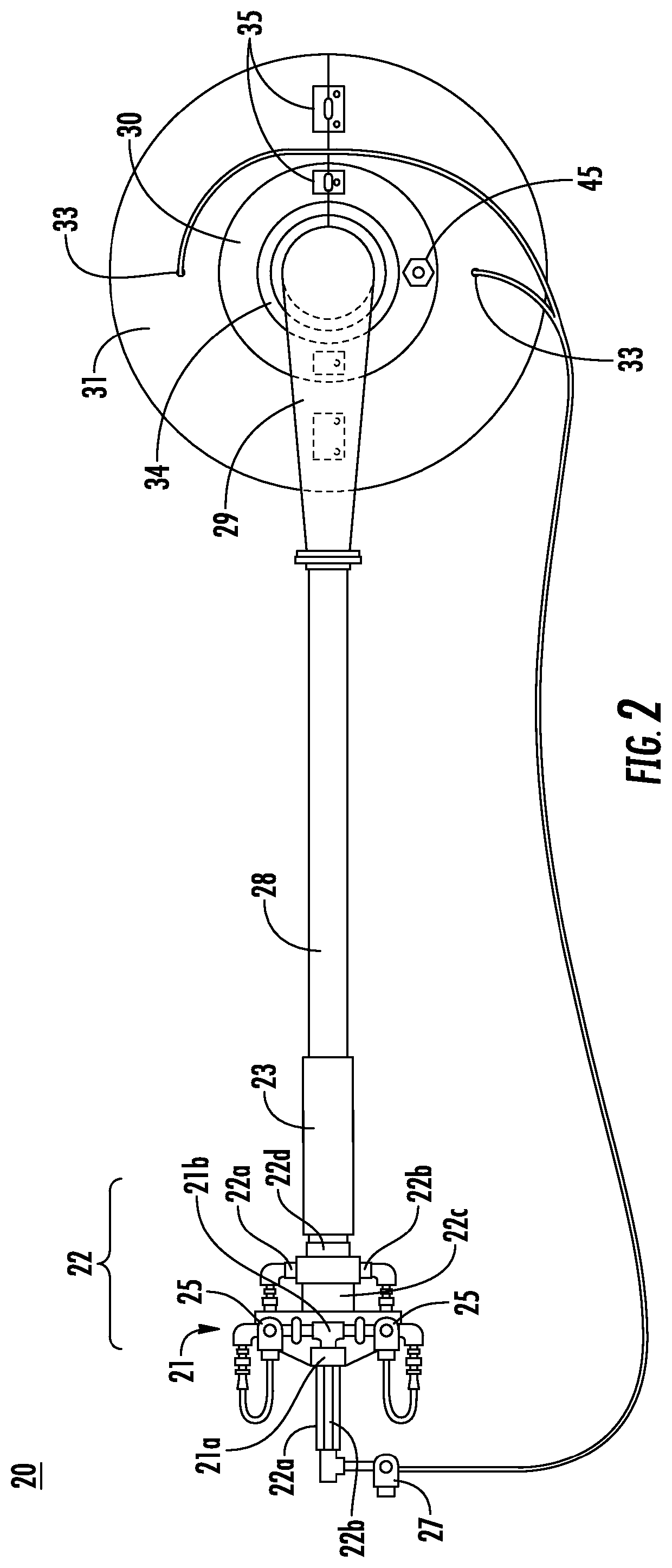
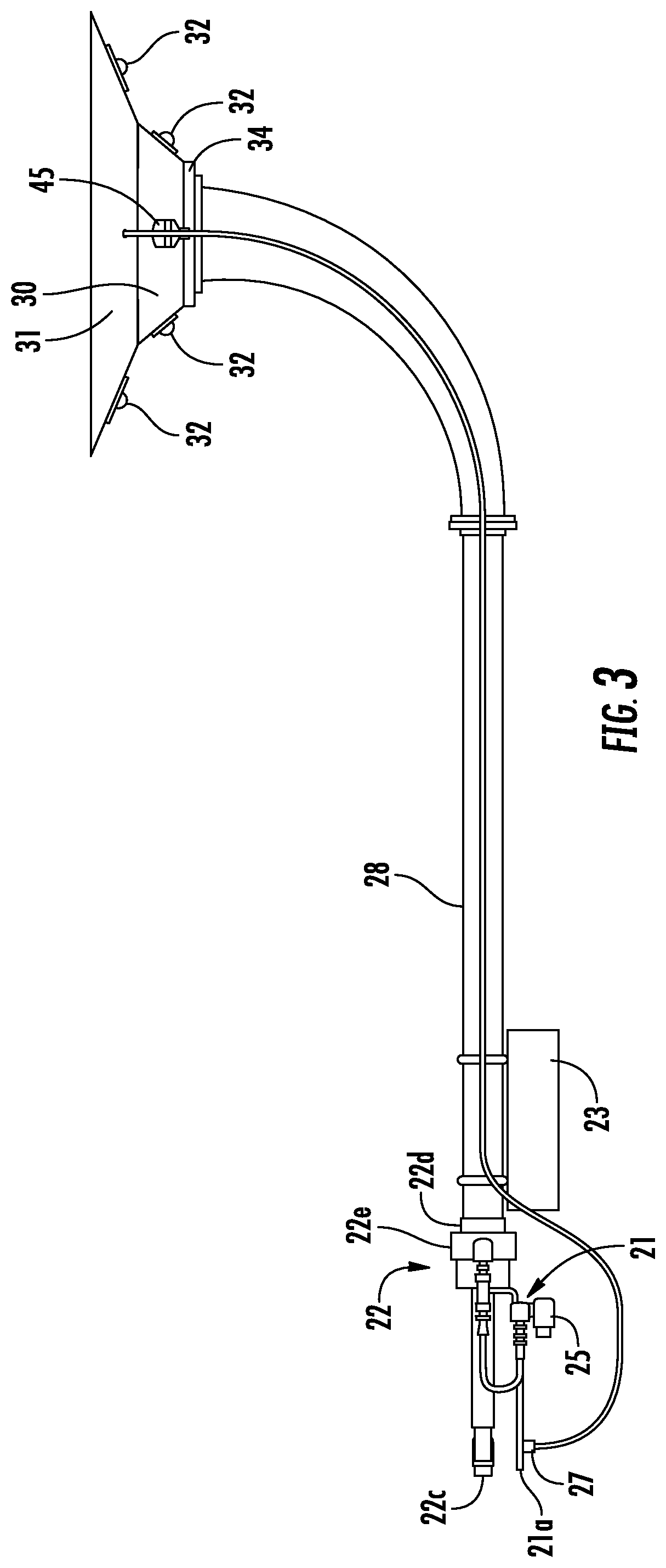
[0019]Generally, the mobile combustion cleaning system (generally referred to herein as reference number 10) and method 80 for practicing the invention referenced herein includes a mobile utility cart 12, a distribution network 20 and a navigation network 40 that provides an improved system for containing a combustion event while directing and focusing an impulse shockwave for an easier and effective off-line cleaning system and method for cleaning fouled hea...


PUM


Abstract

The present invention provides an improved system and method for cleaning a plurality of semi-permeable heat exchange surfaces using an impulse wave which is transmitted by a distribution network and moved around the heat exchange surfaces by a navigational network.

Description

CROSS-REFERENCE TO RELATED APPLICATION[0001]This application claims the benefit of the prior filed U.S. provisional application No. 62 / 773,303 filed Nov. 30, 2018 which is incorporated herein by reference.FIELD OF THE INVENTION[0002]The present invention is broadly directed to an industrial cleaning system and more particularly, to an mobile combustion cleaning system with an improved combustion distribution network which is portable and provides for an improved method for cleaning heat transfer surfaces.BACKGROUND OF THE INVENTION[0003]Industrial heating equipment often utilizes steam produced using heat exchange surfaces for exchanging heat from one source to another, which can then be used to provide steam for providing supply power. Burning of hydrocarbon fuels to produce high pressure steam can result in slagging and fouling of downstream heat transfer surfaces due to the bi-products of the combustion process. In addition, the primary sources of waste heat in industrial facilit...

Claims


Application Information

Patent Timeline
Patent Type & Authority Applications(United States)
IPC IPC(8): F28G11/00F28G15/00
CPCB08B7/0007F28G15/003F28G11/00F28G7/005F28G15/02F28G15/04
Inventor BARRETO, VINCENT P.BARRETO, JORDAN P.
Owner BARRETO VINCENT P
Why Eureka
Try Eureka