
Control device and automatic water sampler including same

a control device and water sampler technology, applied in the direction of testing water, fluid pressure measurement, instruments, etc., can solve the problems of increasing the interval between the rope and the water sampler, affecting the reliability of the specimen, and affecting the accuracy of the specimen, so as to reduce the sampling cost and ensure the reliability and accuracy of the specimen

Active Publication Date: 2020-04-16
GEOENERGY CORP
View PDF0 Cites 5 Cited by
  • Summary
  • Abstract
  • Description
  • Claims
  • Application Information

AI Technical Summary

Benefits of technology

The present patent is about a device that can automatically sample water at a specific level using a sensor. This device is designed to overcome issues caused by sea currents and flow velocities, which can make water sampling difficult and unreliable. By removing this problem, the device ensures that the specimens collected are reliable and accurate, and it reduces the cost of sampling significantly.

Problems solved by technology

However, there are shortcomings in that the bolt-type parts of connection between the rope and the water sampler pose a danger of getting loose when used.
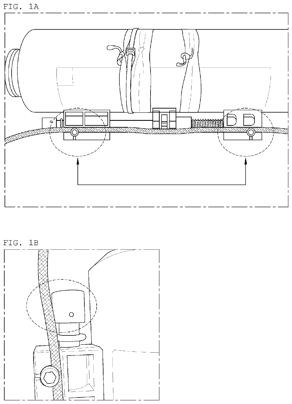
In addition, if the portion to be closed by the messenger is placed in an area with fast tidal currents as illustrated in FIG. 1B, the interval from the rope may increase, failing to sample water in many cases.
Moreover, the handle portion and the rope-connecting part, which are connected to the body without using metallic materials, are weak and thus are easily fractured by minor impacts.
In order to sample water at the desired water level by an existing water sampler, the exact water level at which the water sampler is positioned needs to be recognized, but sea currents and the like make it difficult to recognize the exact water level at which the water sampler is positioned.
However, this approach has a problem in that, in addition to increased costs, the water sampler needs to operated manually in each case.

Method used


Image

  • Control device and automatic water sampler including same
  • Control device and automatic water sampler including same
  • Control device and automatic water sampler including same

Examples


Embodiment Construction

Technical Problem

[0017]An aspect of the present disclosure is to provide a water sampler wherein water can be sampled at the exact water level necessary for water sampling, and control for water sampling can be accurately conducted even without moving a separate messenger by a rope.

Technical Solution

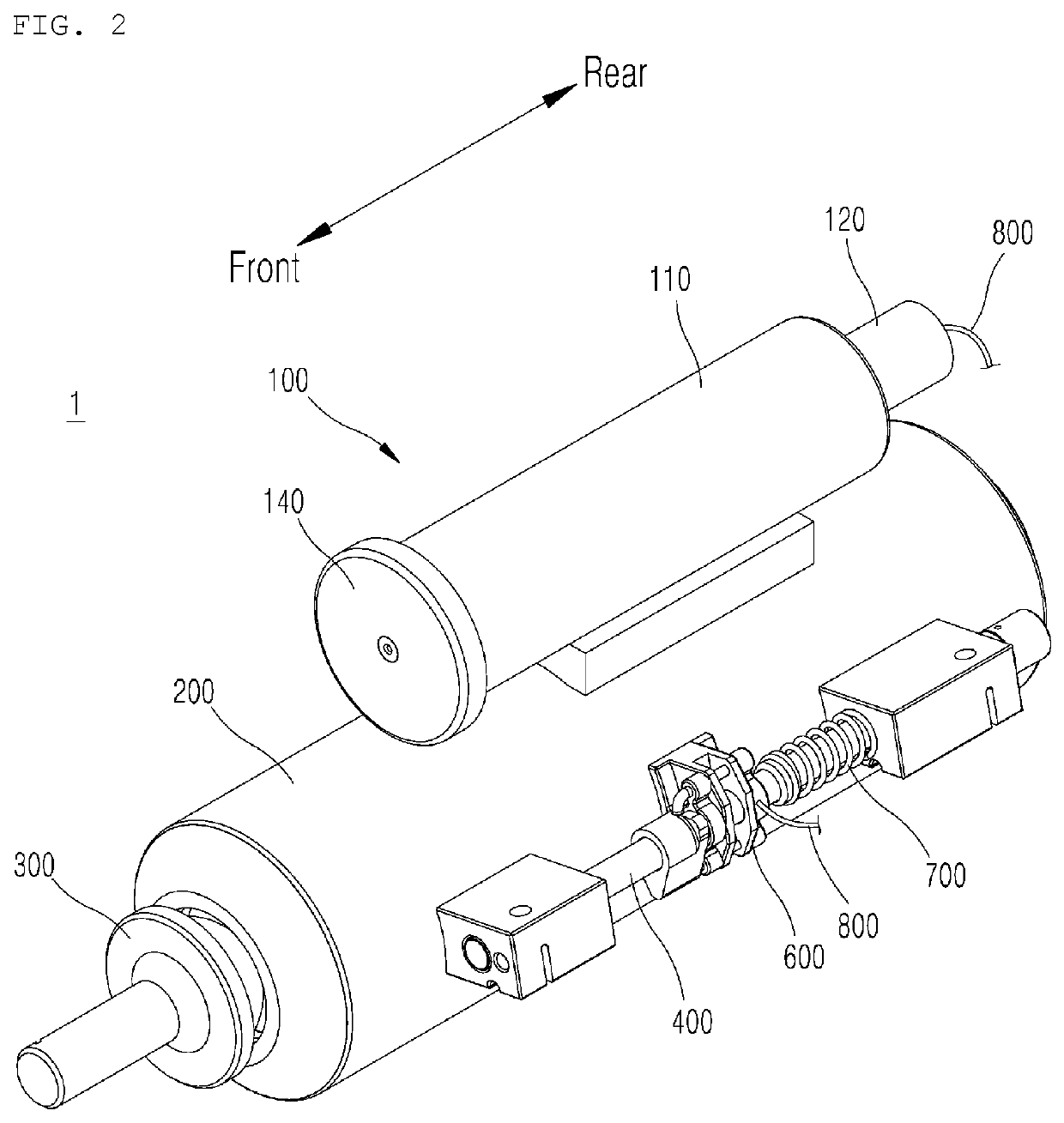
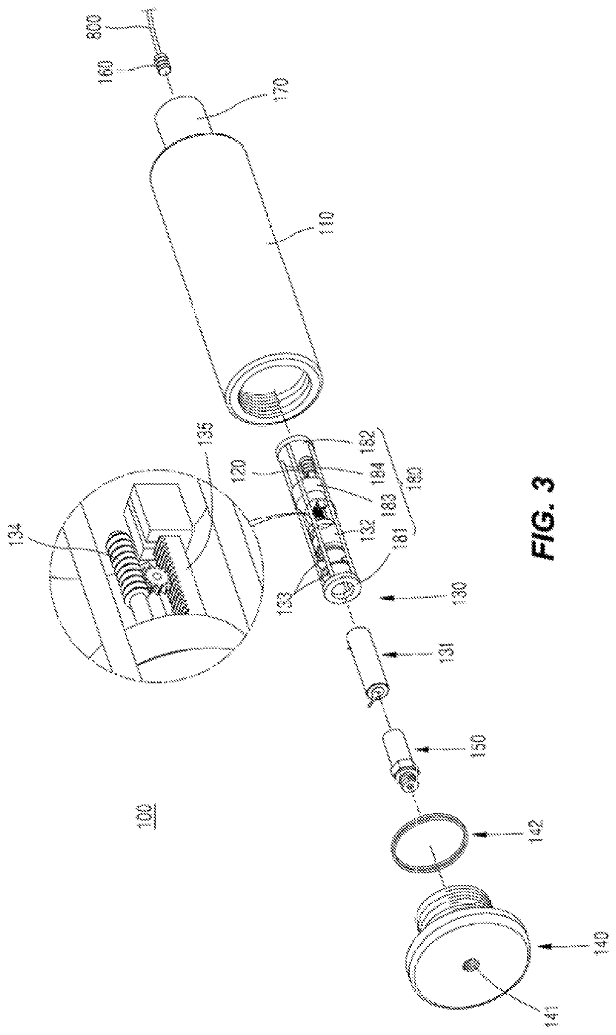
[0018]In accordance with an aspect of the present disclosure, there is provided an automatic water sampler including: a body immersed in water so as to sample seawater or fresh water, the body having an inflow port and a sampling space provided therein; an opening / closing cap configured to open / close the inflow port; a control rod coupled to one side of the body to be able to make reciprocating movements; a first wire having one end connected to the opening / closing cap and the other end engaging with one side of the control rod, the opening / closing cap closing the inflow port when the first wire disengages from the control rod; a first housing coupled to the body and having a containing ...


PUM

PropertyMeasurementUnit
pressureaaaaaaaaaa
attractive forceaaaaaaaaaa
repulsive forceaaaaaaaaaa

Abstract

An automatic water sampler is disclosed. The automatic water sampler of the present invention comprises: a driving unit operated according to the pressure measured by a pressure sensor; a driving magnet approaching a driven magnet according to the operation of the driving unit; and a first wire unlocked by a control rod according to the movement of the driven magnet. The present invention can provide an automatic water sampler, which improves inaccuracy due to conventional interference of an ocean current, flow velocity, and the like, and manual water sampling by depth by automatically sampling water at the correct depth recognized through a pressure sensor, thereby enabling reliability and accuracy of a sample to be ensured and sampling expenses to be remarkably reduced.

Description

CROSS-REFERENCES TO RELATED APPLICATIONS[0001]This application claims priority to and is a continuation of International Patent Application No. PCT / KR2018 / 004427, filed Apr. 17, 2018; which claims priority from Korean Patent Application No. KR 10-2017-0049966, filed Apr. 18, 2017, the entire contents of which are hereby incorporated by reference in their entirety for all purposes.TECHNICAL FIELD[0002]The present disclosure relates to a control device and an automatic water sampler including the same and, more particularly, to an automatic water sampler wherein the same is immersed in water to sample seawater or fresh water, a control rod moves such that an opening / closing cap seals the body thereof, and the same is particularly configured to sample water at a desired water level.BACKGROUND OF THE INVENTION[0003]Water samplers are equipment for sampling seawater or fresh water and are indispensable to analyzing water quality or sampling microorganisms or small plankton.[0004]Existing...

Claims


Application Information

Patent Timeline
Patent Type & Authority Applications(United States)
IPC IPC(8): G01N1/14G01N33/18
CPCG01N33/18G01N1/14G01N35/1097G01C13/008G01D5/06G01L7/00G01N1/12G01N1/10
Inventor KIM, HONG SUNMYUNG, CHEOL SOO
Owner GEOENERGY CORP
Learn More