Microscope and method for microscopic imaging of an object

a microscopic imaging and object technology, applied in the field of microscopic imaging of objects, can solve the problems of virtually preventing the change of setting during the experiment, cumbersome and precise setting of the correction optical unit, and loss of quality due to spherical aberration, and achieves the effect of little radiation damag

Active Publication Date: 2020-04-09
CARL ZEISS MICROSCOPY GMBH
View PDF0 Cites 4 Cited by
  • Summary
  • Abstract
  • Description
  • Claims
  • Application Information

AI Technical Summary

Benefits of technology

[0012]Absolute values of the spherical aberration need not be known in the method. The method relates to a first region, for which the spherical aberration is corrected or correctable by the correction optical unit. By way of reference to this first region and by ascertaining the phase difference and by using the relationship between the phase difference and the change in the spherical aberration caused thereby, the correction optical unit can very easily be set such that the object is imaged with as little spherical aberration as possible in the second region, too. In embodiments, the correction optical unit is first set in such a way that the first region is imaged with as little spherical aberration as possible. By way of example, a region of the object that is known in terms of its refractive index or an easily accessible region of a sample can be used to this end. Consequently, the first region can be selected in such a way that an image with little spherical aberration or with completely compensated spherical aberration is obtained with little outlay and quickly. Then, without further outlay, the method supplies a low-aberration or aberration-free image of the second region, too, by virtue of the phase contrast imaging being performed first and the appropriate setting for the correction optical unit then being obtained for the second region, taking into account the relationship between the change in the spherical aberration and phase contrast. Consequently, the combination of phase contrast imaging and use of a relationship reproducing the change in the spherical aberration allows a particularly simple procedure. In a particularly preferred embodiment, the relationship specifies a setting of the correction optical unit as a function of the phase contrast, more particularly the change in the setting. Thus, the change in the spherical aberration is directly converted into a setting of the correction optical unit.
[0016]A further advantage is that determining the phase difference by quantitative phase contrast imaging causes little or no damage to the object since the radiation used to this end does not interact with the object, or only interacts weakly therewith.
[0034]In particular, the second region is the region of the object that is of interest for the examination to be carried out. As a rule, the second region has a refractive index that differs from the refractive index in the first region because otherwise there would be no need for correcting the spherical aberration. Usually, the refractive index in the second region is unknown, and so purely determining the phase difference between the first region and the second region helps to optimize the spherical aberration for imaging the entire object.
[0040]In order to protect the sample from radiation damage, it is preferable for the phase difference to be determined by means of quantitative phase contrast imaging, with the radiation for the quantitative phase contrast imaging optionally lying in the infrared range. Quantitative phase contrast imaging is known for causing little radiation damage in the object. This is particularly successful if infrared radiation is used. Further, the use of infrared radiation is advantageous in that an interaction with some fluoresced substances can be avoided within the scope of fluorescence imaging.

Problems solved by technology

Excellent imaging quality is becoming ever more important for this, and so losses in the quality on account of spherical aberration are no longer accepted.
Until now, it has been cumbersome to exactly set the correction optical unit, which usually is a so-called correction ring at the objective matching the requirements of the object carrier or of the object.
Moreover, changing the setting during the experiment is virtually precluded.

Method used


Image

  • Microscope and method for microscopic imaging of an object
  • Microscope and method for microscopic imaging of an object
  • Microscope and method for microscopic imaging of an object

Examples


Embodiment Construction

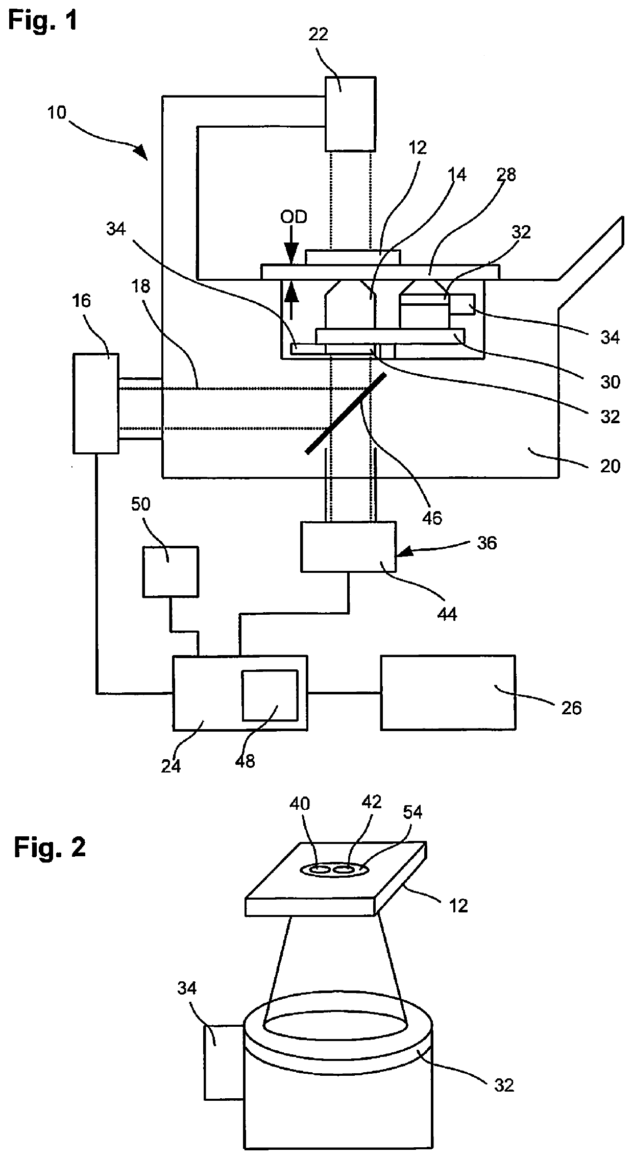
[0048]A microscope 10 facilitates imaging of an object 12. The radiation reflected or transmitted by the object 12 is collected by an objective 14 and imaged on an imaging detector 16 by means of an imaging beam path 18. The objective 14, the imaging detector 16 and / or the imaging beam path 18 are arranged within the housing 20 of the microscope 10. The imaging beam path 18 may be embodied for various types of imaging of the object 12. By way of example, the object 12 can be recorded in the wide field or by means of a scanning imaging method. Further, the microscope 10 may be embodied for fluorescence measurements. Depending on the type of employed imaging, the imaging beam path 18 comprises various optical elements and / or further components, such as, e.g., a scanning device for deflecting radiation. These components are not illustrated in FIG. 1. The object 12 can be illuminated, for example with a reflected-light light source or with the transmitted-light light source 22 illustrat...


PUM


Abstract

A microscope for imaging an object, comprising a lens assembly, which defines an optical axis and a focal plane perpendicular thereto, and correction optics, which are adjustable for adjustment to a depth position and which correct a spherical aberration on the lens assembly which occurs during imaging of the object at a specific depth position of the focal plane. The microscope may be used to determine a phase difference of radiation from a first lateral region and a second lateral region of the object, and to use a previously known connection between the phase difference and a modification of the spherical aberration caused thereby in order to determine an adjustment value of the correction optics, such that the spherical aberration is reduced when imaging the second region.

Description

PRIORITY CLAIM[0001]The present application is a National Phase entry of PCT Application No. PCT / EP2018 / 056434, filed Mar. 14, 2018, which claims priority from German Patent Application 10 2017 105 928.8, filed Mar. 20, 2017, the disclosures of which are hereby incorporated by reference herein in their entirety.FIELD OF THE INVENTION[0002]The invention relates to a method for microscopic imaging of an object by means of a microscope comprising an objective including a correction optical unit. The objective defines an optical axis and a focal plane perpendicular thereto. The correction optical unit of this objective is adjustable to a depth position to correct a spherical aberration occurring when imaging the object at this depth position of the focal plane. Further, the invention relates to such microscope.BACKGROUND OF THE INVENTION[0003]Microscopes often need to have a high degree of flexibility in research since very different types of experiments are carried out. Here, there may...

Claims


Application Information

Patent Timeline
Patent Type & Authority Applications(United States)
IPC IPC(8): G02B21/36G02B21/14G02B21/02G02B27/00
CPCG02B27/0025G02B21/02G02B21/365G02B21/14G01M11/0257
Inventor GOEGLER, MICHAELOHRT, THOMASSTICKER, MARKUS
Owner CARL ZEISS MICROSCOPY GMBH
Why Eureka
Try Eureka