Eureka AIR delivers breakthrough ideas for toughest innovation challenges, trusted by R&D personnel around the world.

Scooter steering lock

a technology for steering locks and scooters, applied in the direction of anti-theft cycle devices, cycle equipment, cycles, etc., can solve the problems of not being able to take scooters indoors, not always practical or convenient, and certain establishments or businesses that do not allow scooters to be taken indoors

Pending Publication Date: 2020-04-02
RAZOR USA
View PDF9 Cites 2 Cited by
  • Summary
  • Abstract
  • Description
  • Claims
  • Application Information

AI Technical Summary

Benefits of technology

The present disclosure describes an improved locking mechanism for securing a scooter in a quick and convenient manner. This mechanism can be attached to the scooter steering assembly and can include a wheel of the scooter that is steerable. The wheel can be locked in place using the locking mechanism, making it difficult to ride without unlocking. This mechanism is easy for the user to actuate and helps to prevent theft. Additionally, the scooter includes a lock actuator that prevents rotation of the locking shaft when in a locked state. This improves security and prevents accidental unlocking of the scooter.

Problems solved by technology

For example, certain establishments or businesses do not allow scooters to be taken indoors.
In this situation and in many others, the scooter can be left unattended by the user.
While precautions can be taken to prevent theft, such as chaining the scooter to an immovable object, such precautions are not always feasible or convenient.
The scooter may not be designed for use with a chain, finding an appropriate immovable object can be problematic, carrying the chain and / or securing the scooter to the immovable object may be inconvenient, and / or the user may be too hurried or careless to properly secure the scooter.
Indeed, some scooters are rented (e.g., on a short-term and / or shared basis), so the user of the scooter may not be the owner of the scooter, which may make it less likely that the user will properly secure the scooter—especially if securing the scooter is time consuming and / or inconvenient.
Scooters left unattended for limited or extended times can be subject to theft or unauthorized use.
Once the wheel is locked in place (e.g., in a turning position), the scooter may be difficult to ride without unlocking.
Accordingly, the scooter can be a less desirable target for theft.

Method used


Image

  • Scooter steering lock
  • Scooter steering lock
  • Scooter steering lock

Examples


example operation

[0096]Operation and assembly of the locking mechanism 150 is described with reference to FIGS. 12-15. For purposes of presentation, the outer housing 154 is not shown in these figures.

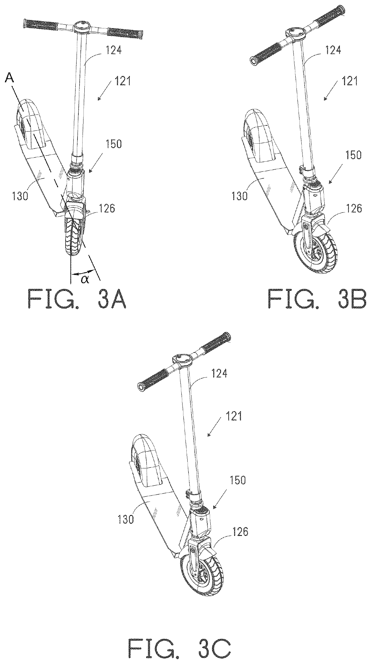
[0097]FIG. 12A shows the front wheel 126 in a right steering position. The front wheel 126 is connected with the locking shaft 162 and the locking shaft 162 is connected with the steering column 124. This can form the steering assembly 121, which can be a generally rigid and / or controllable by the handlebars. The locking shaft 162 is assembled within the header tube 134 (e.g., within the internal space 136) and the projection 164 assembled within the locking recess 135. The locking shaft 162 can rotate (e.g., clockwise and / or counterclockwise) within the header tube 134. The amount of rotation of the locking shaft 162 relative to the header tube 134 can be limited by the physical interference of the projection 164 with the sides of the locking recess 135. The projection 164 can rotate into the wing por...


PUM


Abstract

An improved locking mechanism for securing a scooter or other vehicle. The locking mechanism can secure a wheel of the scooter in a left or right steering position. The locking mechanism can be manually actuated by the user, such as by a foot or hand of the user. Once the wheel is secured in place, the scooter may be difficult to ride without unlocking. The locking mechanism can be unlocked through a wireless connection with a remote control (e.g. a phone).

Description

CROSS REFERENCE[0001]This application claims the benefit of U.S. Patent Application No. 62 / 738,535, filed Sep. 28, 2018, and U.S. Patent Application No. 62 / 792,327, filed Jan. 14, 2019, each of which are hereby incorporated by reference in their entirety.BACKGROUNDField[0002]This disclosure generally relates to steerable personal vehicles such as two, three and four-wheeled scooters and other personal vehicles.Certain Related Art[0003]Scooters and other personal vehicles (referred to herein generically as “scooters”) come in both motorized and non-motorized types and have been popular for decades as lightweight, alternative means of transportation. The portability of scooters provides many advantages. Scooters can be convenient to park, carry or stow when not in use and can be easily deployable again for riding.SUMMARY OF CERTAIN FEATURES[0004]Despite the above-mentioned conveniences, scooters can also have certain downsides. For example, certain establishments or businesses do not ...

Claims


Application Information

Patent Timeline
Patent Type & Authority Applications(United States)
IPC IPC(8): B62H5/06B62H5/20
CPCB62K3/002B62H5/06B62H5/20B62K11/00B62K2202/00B62H5/04B62H5/00
Inventor HUANG, JOEY CHIH-WEICHEN, ROBERT
Owner RAZOR USA
Why Eureka
Eureka Blog
Learn More