
Vise with magnet

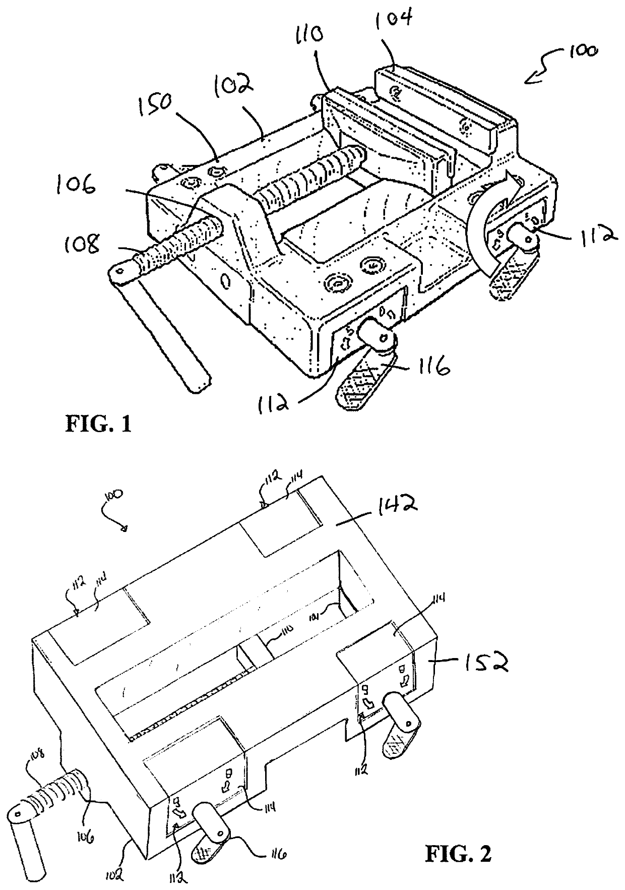
a vise and magnet technology, applied in the field of vises, can solve the problems of cumbersome user, difficult to secure work pieces on a work table or work surface during the manufacturing process, unsatisfactory errors or flaws in finished products, etc., and achieve the effect of convenient and quick securement of a vise to a work surfa

Active Publication Date: 2022-02-22
JPW IND
View PDF11 Cites 2 Cited by
  • Summary
  • Abstract
  • Description
  • Claims
  • Application Information

AI Technical Summary

Benefits of technology

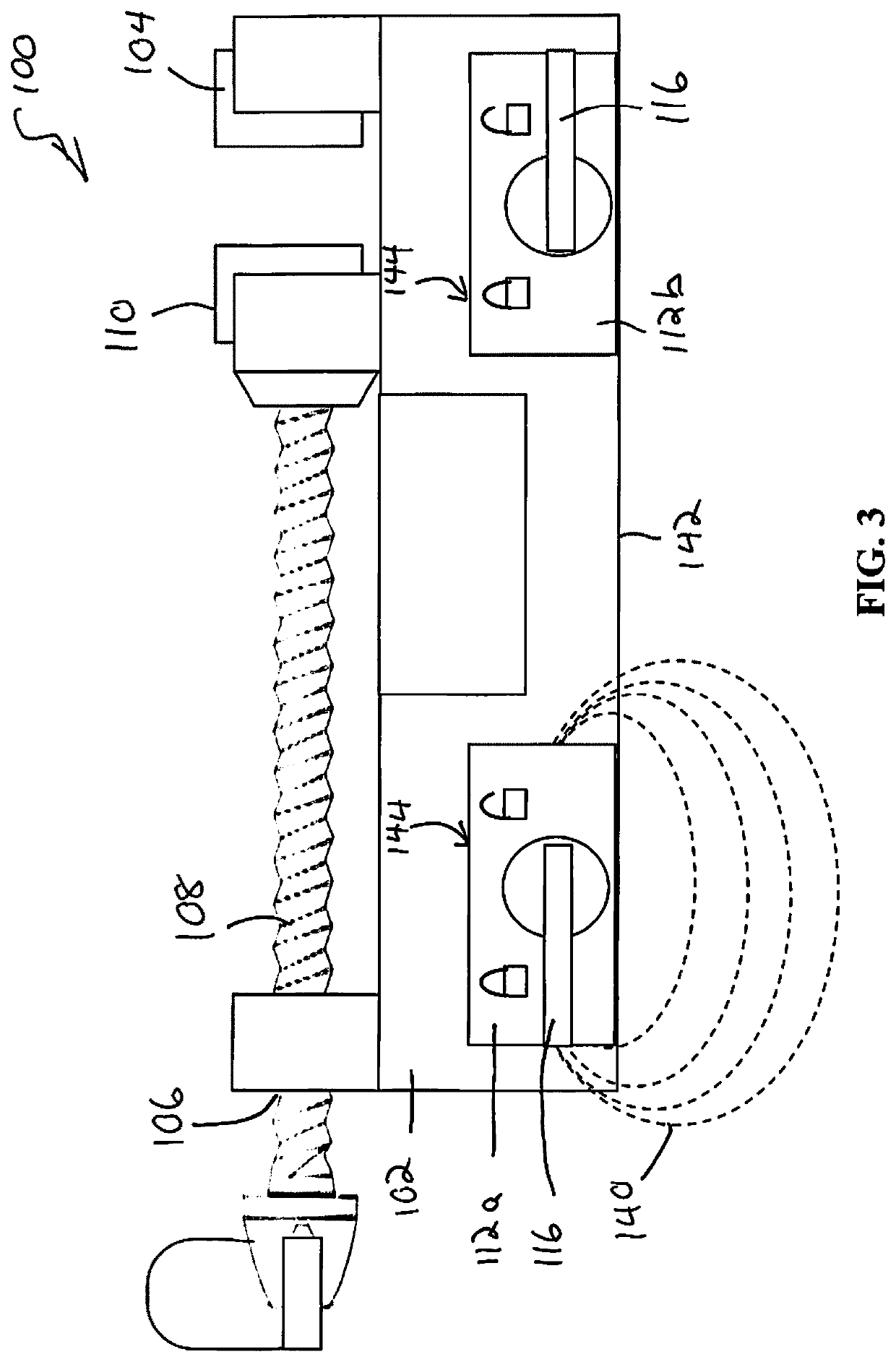
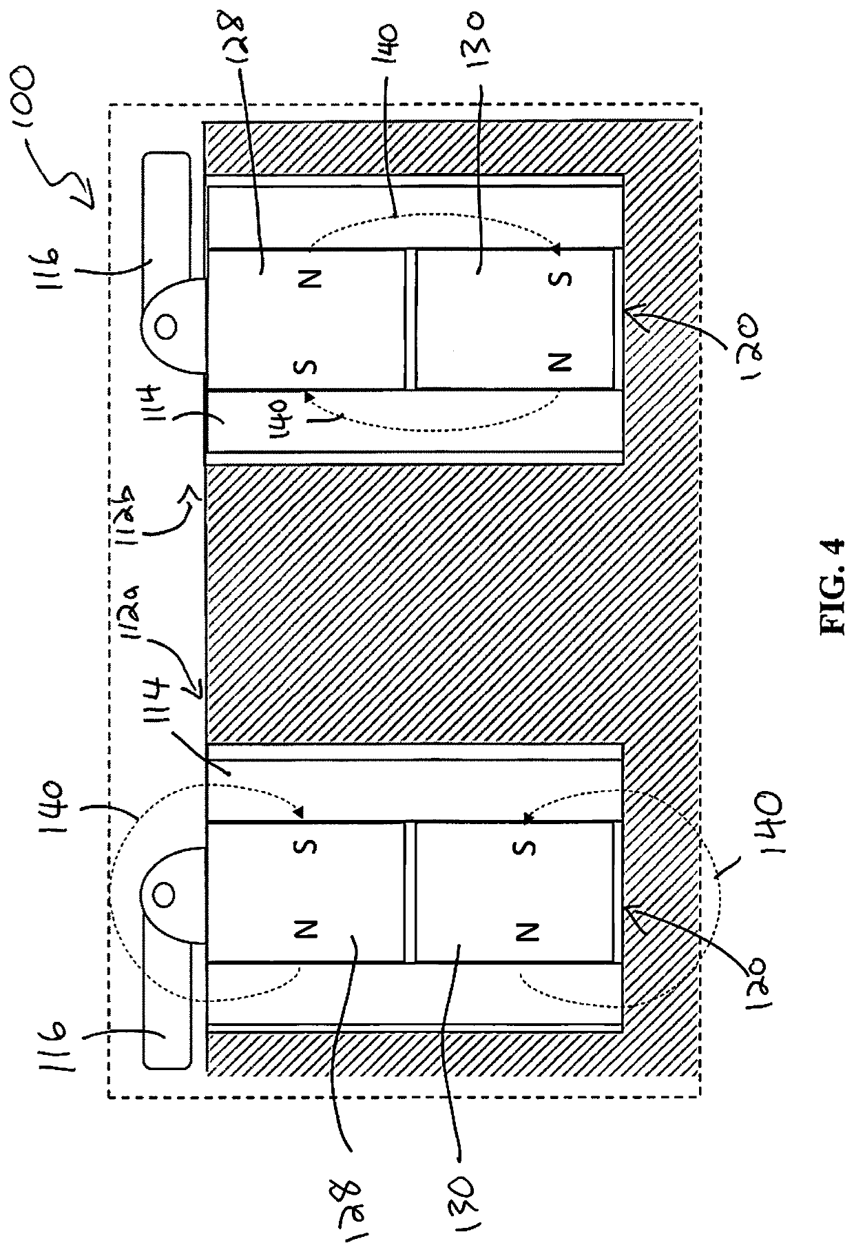
The patent describes a device that uses a magnetic field to secure a vise to a magnetically permeable or ferromagnetic surface. This eliminates the need for additional securing mechanisms and allows the vise to be placed in multiple positions on the surface. The device provides a quick and convenient way to secure a vise to a work surface.

Problems solved by technology

It is often desirable to retain the work piece in a desired position on a work table or work surface, or generally prevent movement of the work piece during the manufacturing or fabrication process, as movement of the work piece can produce undesirable errors or flaws in the finished product.
Securing work pieces on a work table or work surface during the manufacturing process can be difficult as work pieces can come in a variety of differing shapes, sizes, and materials.
Common ways of retaining a work piece on a work surface include a user manually holding the work piece in a desired position, which can be cumbersome for the user.
Manual pressure to hold the work piece in place is often times not sufficient to maintain the work piece in a desired position once the work piece is engaged by a tool.
However, these solutions can typically provide a limited number of positions on the work surface where a work piece can be retained and / or cumbersome fixation mechanisms to secure a clamp, vise, or other retaining member to various positions on the work surface.
Such custom work surfaces or work tables can also be costly to manufacture.
The weight of the vises can make them difficult to handle or maneuver, which is undesirable.
Using mechanical fasteners to secure the vise to the work surface can be cumbersome and time consuming and can limit the possible orientations of the vise, and thus the work piece, on the work surface.

Method used


Image

  • Vise with magnet
  • Vise with magnet
  • Vise with magnet

Examples


Embodiment Construction

[0028]While the making and using of various embodiments of the present disclosure are discussed in detail below, it should be appreciated that the present disclosure provides many applicable inventive concepts that are embodied in a wide variety of specific contexts. The specific embodiments discussed herein are merely illustrative of specific ways to make and use the invention and do not delimit the scope of the invention. Those of ordinary skill in the art will recognize numerous equivalents to the specific apparatus and methods described herein. Such equivalents are considered to be within the scope of this disclosure and are covered by the claims.

[0029]In the drawings, not all reference numbers are included in each drawing, for the sake of clarity. In addition, positional terms such as “upper,”“lower,”“side,”“top,”“bottom,” etc. refer to the apparatus when in the orientation shown in the drawing. A person of skill in the art will recognize that the apparatus can assume different...


PUM

PropertyMeasurementUnit
magnetic fieldaaaaaaaaaa
magnetic assembliesaaaaaaaaaa
magneticaaaaaaaaaa

Abstract

A vise for securing a work piece is disclosed which includes a base. A first jaw piece and a second jaw piece can be disposed on the base, at least one of the first and second jaw pieces movable on the base such that the first and second jaw pieces are moveable toward and away from one another. A magnetic assembly can be positioned on the base and configured to produce a magnetic field that extends beyond the base to secure the vise to a magnetically permeable or ferromagnetic work surface. The magnetic assembly can be operable to alternate between an active mode and an inactive mode. The magnetic assembly can produce a magnetic field when the magnetic assembly is in the active mode to secure the vise to a magnetically permeable or ferromagnetic work surface.

Description

CROSS-REFERENCES TO RELATED APPLICATIONS[0001]This application is a non-provisional of U.S. Patent Application No. 62 / 675,202 filed May 23, 2018 entitled WORK TABLE AND CLAMPING VISE WITH MAGNETIC ASSEMBLY, which is hereby incorporated by reference in its entirety.[0002]A portion of the disclosure of this patent document contains material that is subject to copyright protection. The copyright owner has no objection to the reproduction of the patent document or the patent disclosure, as it appears in the U.S. Patent and Trademark Office patent file or records, but otherwise reserves all copyright rights whatsoever.STATEMENT REGARDING FEDERALLY SPONSORED RESEARCH OR DEVELOPMENT[0003]Not ApplicableREFERENCE TO SEQUENCE LISTING OR COMPUTER PROGRAM LISTING APPENDIX[0004]Not ApplicableBACKGROUND OF THE INVENTION[0005]The present disclosure relates to vises for use in the manufacture or fabrication of a work piece. More specifically, the disclosure relates to vises for use in retaining wor...

Claims


Application Information

Patent Timeline
Patent Type & Authority Patents(United States)
IPC IPC(8): B25B1/00B25B1/24H01H36/00B25B1/02B25B1/10B25B11/00B25H1/02F16B1/00
CPCB25B1/2484B25B1/02B25B1/103B25B11/002B25H1/02F16B1/00H01H36/0073F16B2001/0035B25H1/0071F16B2200/83
Inventor COLEMAN, MICAHWEBER, CHARLES
Owner JPW IND
Learn More