
Drill string component coupling device

Inactive Publication Date: 2016-12-15
SANDVIK INTELLECTUAL PROPERTY AB
View PDF1 Cites 4 Cited by
  • Summary
  • Abstract
  • Description
  • Claims
  • Application Information

AI Technical Summary

Benefits of technology

The present invention provides a safety coupling device for a drill string assembly, which is a coupling arrangement for positioning at the interface region between a drill string rotational drive unit and an axially rearward section of the drill string. The coupling unit is designed to be conveniently mounted and dismounted from the drive unit and / or drill string components using readily available non-specific tools in a quick and convenient manner. Additionally, the invention provides a safety joint coupling compatible for use with existing drill string drive units and drill string components without the need to specifically modify the radially outward facing regions of such units and components.

Problems solved by technology

Additionally, it is typically unavoidable to have to service the drill head or other tools at the lowermost end of the drill string at regular intervals during drilling.
Due to a large number of breakout manipulations required, it is not uncommon for the drill string to become unintentionally decoupled from the bull shaft at the drive unit.
Accidental decoupling of the string represents a significant safety hazard as the entire string becomes unanchored and may either be lost down the borehole (when lowered under gravity) or to spill uncontrollably adjacent the drive unit if in an inclined drilling orientation.
However, existing coupling devices suffer from a number of significant disadvantages.
Accordingly, it is often difficult and in some cases impossible to conveniently adapt existing drill string assemblies to fit a safety coupling device of the type found in the art.
Additionally, conventional couplings require specific tools to enable detachment and decoupling which can be problematic if the tools become damaged or are unavailable on-site.
Additionally, due to the significant torques encountered during drill string extractions, it is not uncommon for existing safety couplings to fail by becoming decoupled themselves from their region of attachment particularly where such couplings rely on threaded connections and / or are anchored inadequately onto the outside surface of the drill string components.

Method used


Image

  • Drill string component coupling device
  • Drill string component coupling device
  • Drill string component coupling device

Examples


Embodiment Construction

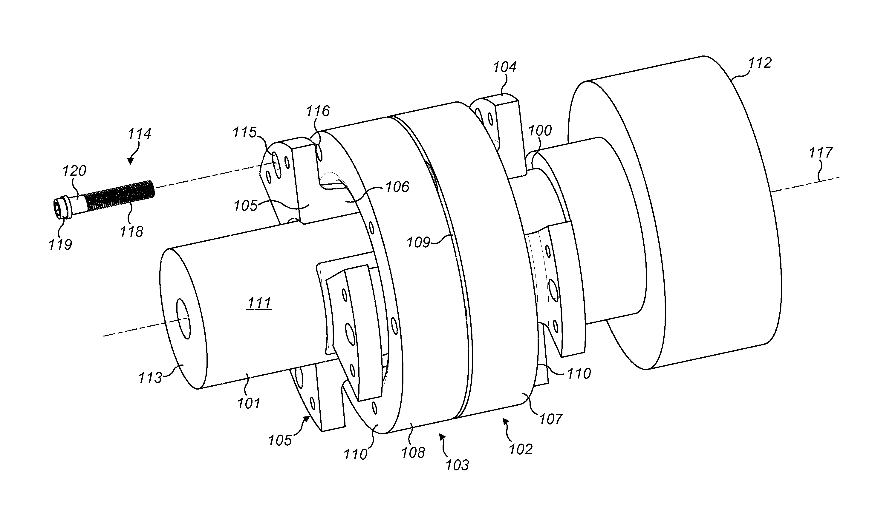
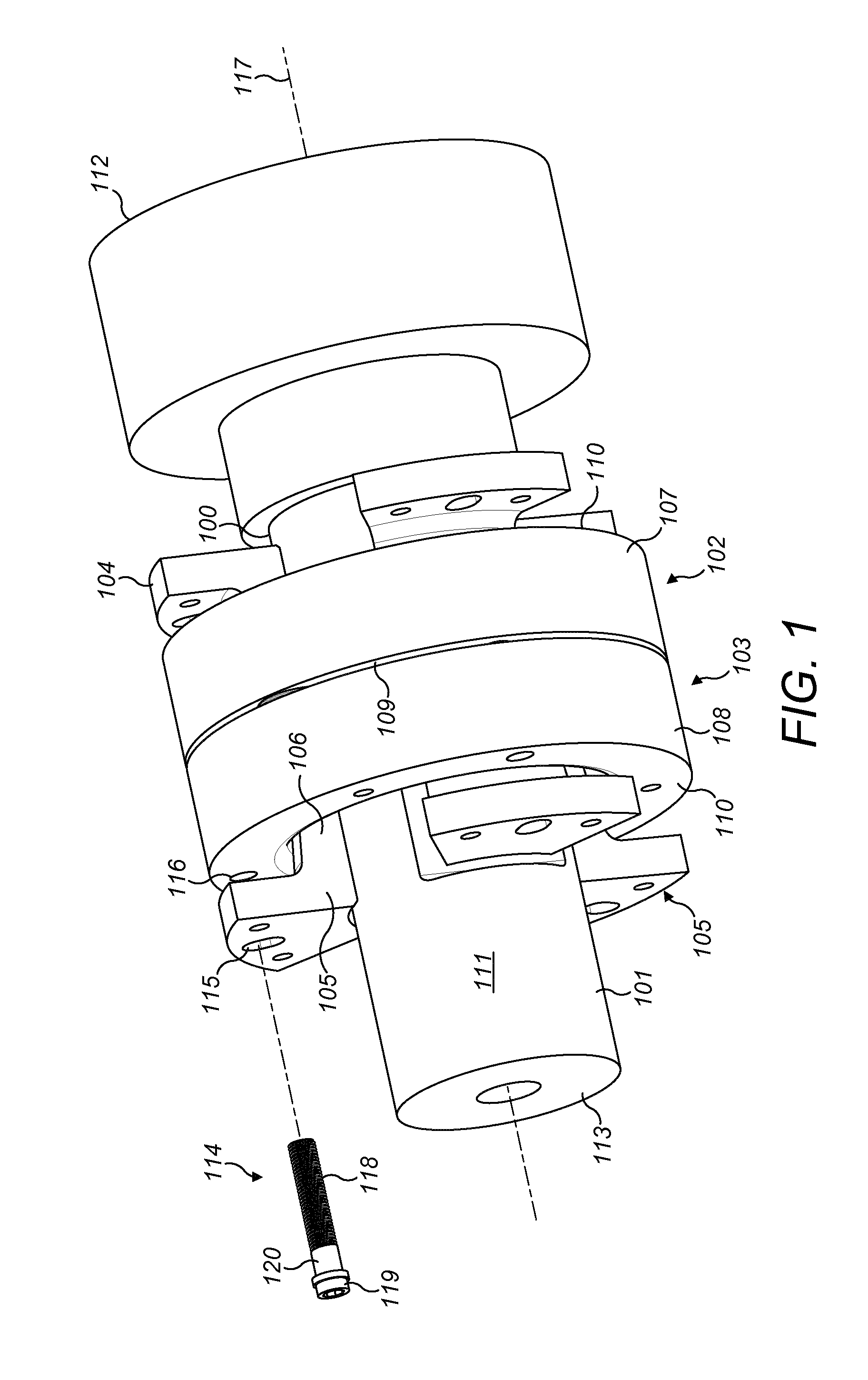
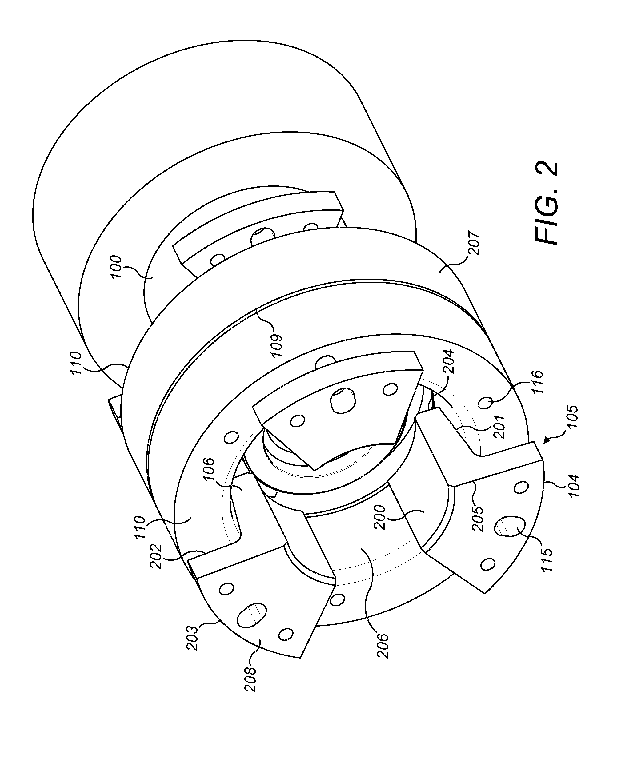
[0029]Referring to FIG. 1, the coupling device comprises generally a first half 102 and a second half 103 positioned at and about an axial joint between two components of a drill string assembly. In particular, the coupling device first and second halves 102, 103 are positioned respectively over a bull shaft 100 that projects axially from a drive unit (not shown) connected to bull shaft 100 at region 112. The second half 103 of the coupling device is secured over a tubular elongate adaptor 101 that is in turn secured to an axially rearwardmost drill rod (not shown) forming part of a drill string (not shown) attached to adaptor 101 at region 113. The present coupling device is configured to be axially locked at each of the cylindrical components 100, 101 and to be axially coupled such that each drill string component 100, 101 is rotatably coupled and prevented from independent rotation about axis 117.

[0030]Coupling device first half 102 comprises a first sleeve 107 and a plurality of...


PUM


Abstract

A drill string coupling device is positionable at a joint within a drill string assembly and, in particular, a drive shaft forming part of a drive unit and an adaptor or axially rearwardmost part of the drill string. The coupling device includes at least one sleeve that is axially locked at one of the drill string components by a plurality of engaging wedges that are positioned between the sleeve and the drill string component. A plurality of rotational stops project axially from the sleeve to engage with a second component of the drill string or an element attached to the second component to rotatably lock the two components of the drill string assembly and prevent independent rotation.

Description

FIELD OF INVENTION[0001]The present invention relates to a drill string component coupling device positionable at a joint within a drill string assembly to rotatably couple a first drill string component to a second drill string component and in particular, although not exclusively, to a coupling device to couple the drill string to a drive unit part of the assembly.BACKGROUND ART[0002]Rotary drilling is conventionally used for drilling mining blast holes or geothermal wells and relies on high rotational speeds and thrust on the drill bit in order to drill the hole. The rotary drill bit is advanced into the bore by successive joining of sections of pipe or rod to create a drill string. The drill rig and in particular the drive unit is located at ground level and is coupled to the drill rods via a ‘bull’ shaft and an intermediate adaptor.[0003]Drill rods, depending on their specific configuration, may weigh between ten to twenty kilograms each and measure approximately two to three m...

Claims


Application Information

Patent Timeline
IPC IPC(8): E21B17/043F16D1/05E21B19/16E21B3/02E21B17/046
CPCE21B17/043E21B3/02F16D1/05E21B19/16E21B17/046E21B3/022
Inventor MALSTAM, JOHANLINDBLOM, ANDERS
Owner SANDVIK INTELLECTUAL PROPERTY AB
Learn More