
Composite joint implant

Active Publication Date: 2020-02-27
ORTHONIKA LTD
View PDF0 Cites 8 Cited by
  • Summary
  • Abstract
  • Description
  • Claims
  • Application Information

AI Technical Summary

Benefits of technology

The present invention provides a composite joint implant for replacing a human knee meniscus that can replicate the shape of a natural meniscus. The implant has a wedge-shaped cross-section and a reinforcing element embedded within it to prevent separation from the implant. The implant also has a recess around its external edge to prevent bulging and detachment of the ligature. The ligature features high stiffness and strength, with low stretch properties, and can form a tube-like construct that encapsulates the entire implant. The technical effects of this invention are anatomical replicas of human knee menisci that can restore natural joint function and minimize complications such as pain and osteoarthritis.

Problems solved by technology

With limited natural repair capabilities, surgical treatment is very common.
However, partial or total removal of the meniscus has detrimental effects on the knee joint, and these treatments increase the contact stresses on the articular surface of the knee joint.
Long-term, there is a high risk of osteoarthritis development after meniscectomy.
In addition to the long term failure rates, meniscus allografts display significantly high costs ($15K / operation), limited availability, sizing problems, risk of infection, and require challenging and complex surgery for initial implantation.
One major challenge with meniscus implants is the ability to mimic the structure-function relationship present within the native tissue and the macro-scale mechanical properties which exhibit unique tensile-compressive properties.
Current implants on the market are limited to partial meniscus replacement due to a lack of a means to mimic this functional property of force translation as well as their inability to anchor the implant within the knee joint.
To date partial meniscus implants and component meniscus systems are not able to provide the function of the native meniscus due to lack of meniscus geometry, structure and lack of an inherent attachment mechanism or ligature.

Method used


Image

  • Composite joint implant
  • Composite joint implant
  • Composite joint implant

Examples


example 1

Preparation of Multifilament Yarn and Fiber

[0100]Fiber and yarn materials were prepared by melt extrusion and reorientation during a multi-stage drawing using a series of heated Godets. High tenacity poly(ester terephthalate) (HT-PET), ultra-high molecular weight polyethylene (UHMWPE), and polypropylene (PP) monofilament were prepared into monofilament fiber and multi-filament yarn through single or multiple hole spinnerets.

example 2

Polymeric Body

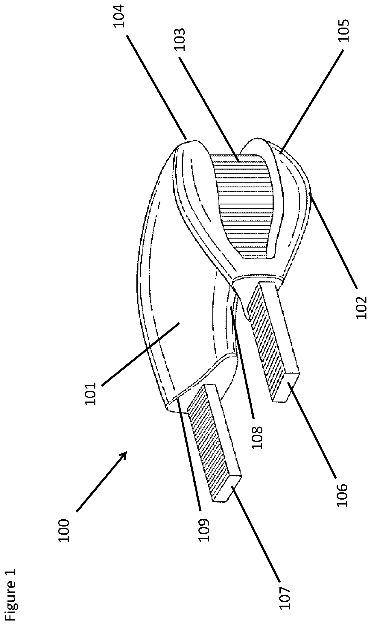
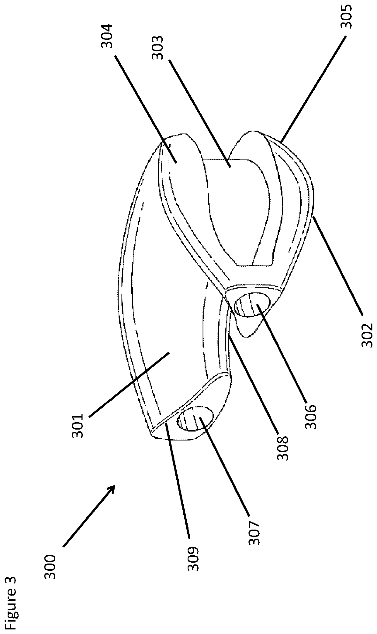
[0101]A polymeric body was shaped and formed into a crescent shaped, semicircular geometry with a trapezoidal, wedge shaped cross section, resembling as closely as possible the anatomical shape of the human natural meniscus, whether the medial or the lateral. The polymeric body features a concave top surface, convex or flat bottom surface. The polymeric body features an internal edge where bottom and top surfaces meet and expand away from each other increasing the thickness of the implant and forming an external edge of the implant. The side of the external edge may feature a recess, cavity or groove which runs at least partly around the entire outer periphery of the body and spans at least a portion of the thickness of the device. The recess can feature a varying depth into the thickness of the body towards the internal edge. The recess can rotate by over 90 degrees and run on the top or bottom surface as it approaches the internal edge at one or both ends of the devi...

example 3

Preparation of Scaffold 1

[0102]Example 2 consisting of the polymeric body and the ligature, reinforcing elements, and scaffold (Examples 3 to 8) can be impregnated using casting, compression molding, solution casting, additive manufacturing or injection molding to fully or partially encapsulate the ligature placed in the external groove of the implant. This can be achieved using injection molding by placing the inlet port for molten polymer around the edge of the polymeric body and encapsulating or coating the textile component. This additional injection molding step would allow Example 2 to be represented in a fully anatomical shape and volume mimicking as close as possible the size and shape of either the medial or the lateral meniscus and also mimic the natural tissue attachment by means of an incorporated ligature. The cavity of the polymeric body can be comprised of a protruding lip on either the top surface, the bottom surface, or both surfaces. The protruding lips of the cavi...


PUM


Abstract

A composite joint implant device replaces or repairs damaged meniscus tissue in an animal or human. In one embodiment, a composite joint implant comprises a polymeric body which is reinforced with a pre-formed engineered ligature mechanism. The ligature reinforces the polymeric body around the circumference and is used for attaching the device within an animal or human body. The ligature mechanism internally supports the transmission of vertical loads into tensile stresses. The ligature mechanism can be coated with a compatible material to promote integration with the polymeric body and coated with an encapsulation material.

Description

CROSS-REFERENCE TO RELATED APPLICATIONS[0001]The present application claims benefit of priority to U.S. Provisional Patent Application No. 62 / 500,006, entitled, “COMPOSITE JOINT IMPLANT,” filed May 2, 2017, which provisional application is incorporated herein by reference in its entirety.COPYRIGHT NOTICE[0002]A portion of the disclosure of this patent document contains material which is subject to copyright protection. The copyright owner has no objection to the facsimile reproduction by anyone of the patent document or the patent disclosure, as it appears in the United States Patent and Trademark Office patent file or records, but otherwise reserves all copyright rights whatsoever.FIELD OF THE INVENTION[0003]The present invention relates generally to implantable composite joint implants and related methods of manufacture and use, and more particularly, to implantable composite joint implants having particular application for repairing, replacing, and / or augmenting a human joint and...

Claims


Application Information

Patent Timeline
IPC IPC(8): A61F2/38A61F2/30
CPCA61F2/3872A61F2/30965A61F2310/00005A61F2002/30464A61F2002/30576A61F2002/30462A61F2002/30754A61B17/562
Inventor MCCULLEN, SETHACCARDI, MARIO ALBERTOAGIUS, MARIA KRISTINAAMIS, ANDREW ARTHUR
Owner ORTHONIKA LTD
Learn More