Actuator equipped with a no back system with inhibition zone

Active Publication Date: 2020-01-30
SAFRAN ELECTRONICS & DEFENSE
View PDF0 Cites 4 Cited by
  • Summary
  • Abstract
  • Description
  • Claims
  • Application Information

AI Technical Summary

Benefits of technology

The invention described in the patent text has several advantages over existing actuators. Firstly, the actuator uses a small number of parts, making it more reliable. Secondly, the actuator takes into account manufacturing tolerances and the value of retraction overtravel by making a difference in amplitude between the first and second angular sectors. The closer the amplitudes of the first and second sectors, the greater the number of pawls and obstacles. The actuator is easier to manufacture when the portion constrained to rotate with the screw has a bushing slidably mounted on the screw, and is improved in braking when it contains a skew roller disk mounted free to rotate about the screw and provided with rollers having axes of rotation that form a non-zero angle with a radial direction passing through one of the ends of the roller. The actuator is simpler to manufacture when the smooth surface is at the periphery of the friction disk.

Problems solved by technology

From the start of opening the movable surfaces, deploying them subjects a movable surface to large forces that tend to cause it to move quickly from its retracted position to its deployed position.
Unfortunately, it is essential to prevent the movable surface from being capable of deploying under the effect of forces that might be exerted on it directly: specifically, an accidental deployment of the movable surface could have consequences for the safety of the airplane that are catastrophic.
The vibration to which the movable surface is subjected in flight can lead to forces of short duration tending to bring the movable surface towards its over-retracted position.
Specifically, if it fails to return to its retracted position, the nacelle would be subjected to large forces resulting from the combination of the internal force holding the movable surface in the over-retracted position plus the vibration and coming from its connection with its actuator instead of the primary lock.
This makes it necessary to install a mechanism for disengaging the anti-extension device, thereby representing a safety risk and also requiring additional control instrumentation.
Those solutions increase the weight and the size of the equipment, which puts a brake on the use of electrical actuators for thrust reversal.

Method used


Image

  • Actuator equipped with a no back system with inhibition zone
  • Actuator equipped with a no back system with inhibition zone
  • Actuator equipped with a no back system with inhibition zone

Examples


Embodiment Construction

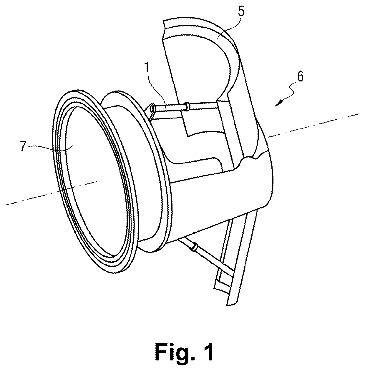
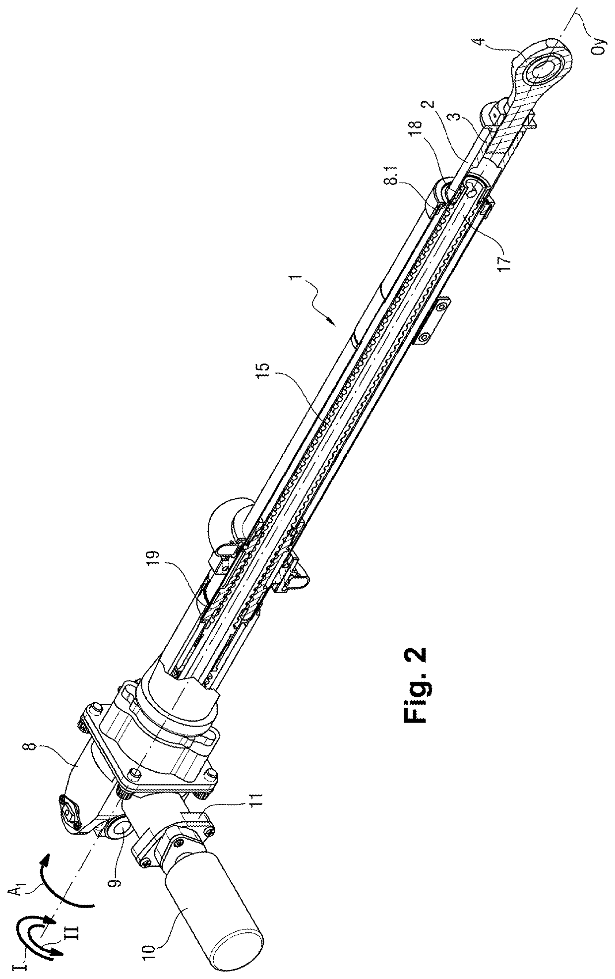
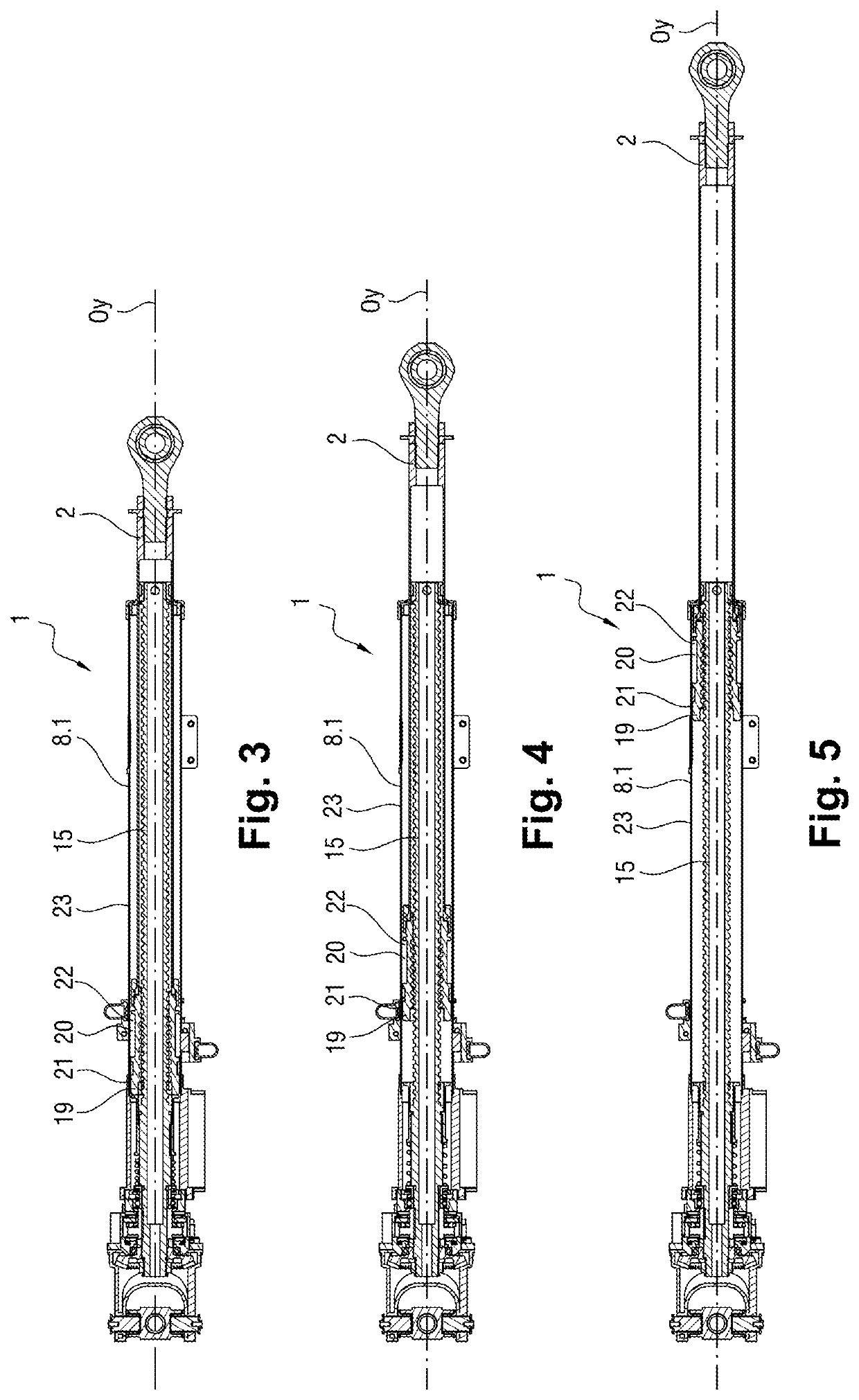
[0035]With reference to FIGS. 1 to 13, the electromechanical actuator of the invention, given overall reference 1, comprises an extension tube 2 having a first end 3 with a ball clevis 4 connected to a movable surface 5 of a thrust reverser 6 of a nacelle 7. The body 8 of the actuator 1 comprises a universal joint 9 hinging the actuator 1 to the turbojet nacelle 7 and a sheath 8.1 in which the extension tube 2 slides between an over-retracted first position (shown in FIG. 3) and a deployed second position (shown in FIG. 5). FIG. 4 shows a retracted third position situated between the over-retracted first position of FIG. 3 and the deployed second position of FIG. 5. The deployed second position corresponds to a position in which the movable surface 5 is completely deployed and is then in contact with a deployment abutment. The retracted third position corresponds to a position in which the movable surface 5 is closed and in which said movable surface 5 bears against sealing gaskets ...


PUM


Abstract

An actuator includes:a screw mounted on a body to pivot;a nut connected to an element for moving, and that is engaged on the screw to be moved between an over-retracted first position and a deployed second position on either side of a retracted third position that is spaced apart from the over-retracted position by a distance corresponding to the screw rotating through a first angular sector; andan anti-extension device comprising a friction disk having at least one smooth surface and an obstacle both for co-operating with at least one pawl, thereby defining both at least one second angular sector of free rotation for the friction disk and also a position for blocking the friction disk.

Description

FIELD OF THE INVENTION[0001]The present invention relates to the field of aviation actuators, and more particularly thrust reverser actuators for jets, and more particularly for turbojets.BACKGROUND OF THE INVENTION[0002]In a conventional thrust reverser system for a turbojet of an aircraft, the nacelle of the turbojet is provided with movable surfaces that can be moved between an over-retracted first position and a deployed second position so as to send a portion of the gas stream produced by the turbojet back towards the front, these positions being situated on either side of a retracted third position for the movable surface. Activating the thrust reverser serves in particular to reduce the distance required by the aircraft for landing. From the start of opening the movable surfaces, deploying them subjects a movable surface to large forces that tend to cause it to move quickly from its retracted position to its deployed position.[0003]Conventionally, the movable surfaces are mov...

Claims


Application Information

Patent Timeline
IPC IPC(8): F02K1/76F16H25/20
CPCF16H25/2015F02K1/763F16H2035/005F16H25/2454F16H25/24F16H25/20
Inventor WERQUIN, MICKAELHAUTECOEUR, JULIENBASTIDE, CHRISTOPHEOMNES, PASCAL
Owner SAFRAN ELECTRONICS & DEFENSE
Why Eureka
Try Eureka