Holographic Reconstruction System Having an Enlarged Visibility Region

Inactive Publication Date: 2010-02-25
SEEREAL TECHNOLOGIES
View PDF0 Cites 3 Cited by
  • Summary
  • Abstract
  • Description
  • Claims
  • Application Information

AI Technical Summary

Benefits of technology

[0009]It is the object of the present invention to provide technical means which enlarge the visibility region optically in an inexpensive manner. When modulating the light wave front, which reconstructs a three-dimensional scene, the effective number of cells in one dimension shall in particular be multiplied in comparison to the respective number of cells in that dimension of the modulator matrix.
[0021]In order to optically enlarge the visibility region according to the object of this invention, first optical deflection means laterally deflect the partial light waves of a strip hologram in one dimension such that the partial light waves appear in a step-like offset manner in the focal plane of the optical focussing means. These deflection means have static angle settings. This has the advantage that a simple spatial frequency filter with a step-like structure of fix apertures can be used in order to separate with high efficiency the same respective diffraction order, which is desired for reconstructing, of each modulated partial light wave from the disturbing parasitic diffraction orders.
[0026]According to a preferred embodiment of this invention, the first optical deflection means can be a prism array with micro prisms, where each matrix section is assigned with a multitude of micro prisms, which direct the partial light waves in a step-like manner according to the structure of the spatial frequency filter. This facilitates a more light-weight design of the projection system and reduces the volume of the hologram projector.
[0033]Considering this, the visibility region can for example be broadened in the spatial division multiplex mode by horizontally stringing together multiple hologram segments, i.e. by increasing the horizontal resolution. In this context, the hologram computation means can compute a larger number of strip holograms for each video hologram in order to increase with the help of the encoding means the vertical resolution in the time division multiplex mode.

Problems solved by technology

A problem is that for enlarging the visibility region the multiple diffraction orders having different intensities are filtered and joined sequentially.
Further, extensive software means are required, e.g. for switching and controlling the apertures.

Method used


Image

  • Holographic Reconstruction System Having an Enlarged Visibility Region
  • Holographic Reconstruction System Having an Enlarged Visibility Region
  • Holographic Reconstruction System Having an Enlarged Visibility Region

Examples


Embodiment Construction

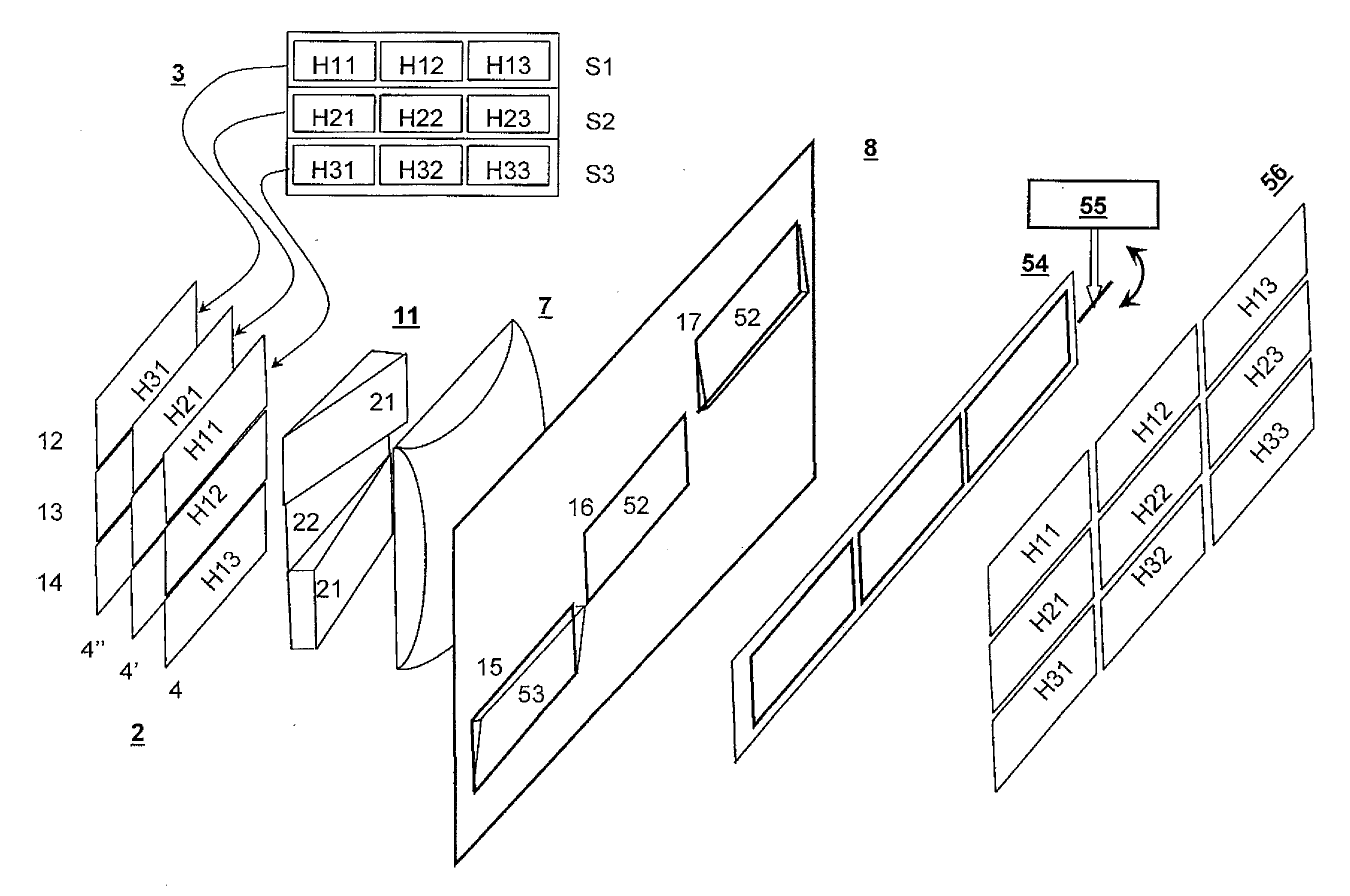
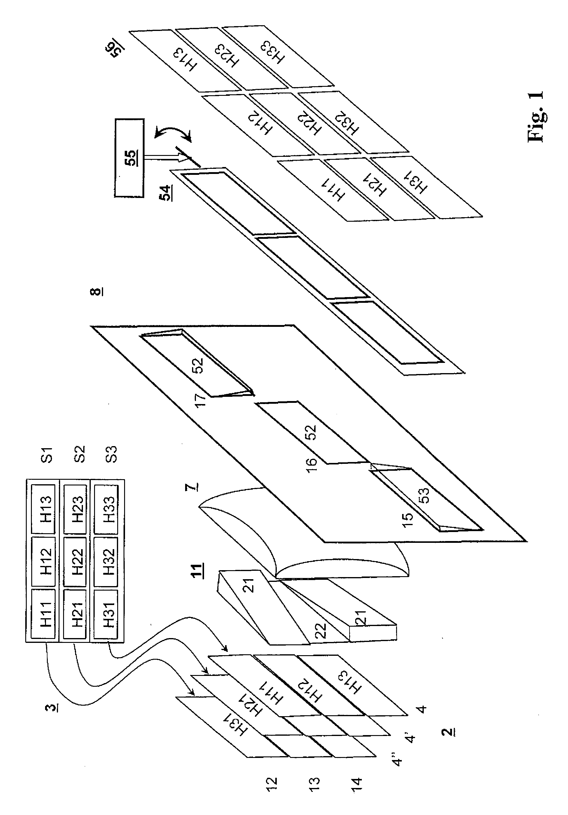
[0053]FIG. 1 illustrates a detail of a holographic reconstruction system 1 for the holographic reconstruction of scenes with a light modulator 2 on which a sequence of video holograms is encoded. Light which is capable of generating interference (not shown) illuminates the modulator cell matrix 4 of a spatial light modulator 2 with m modulator cell rows at n modulator cells each, focussing means, here in the form of a lens 7, and a spatial frequency filter 8.

[0054]According to the present invention, a first optical deflection means, here in the form of a prism array 11, is disposed between the light modulator 2 and the lens 7. Hologram computation means 3 compute for each video hologram strip holograms S1 . . . S3 with hologram segments H11 . . . H33. An encoding device (not shown) encodes one after another the modulator cell matrix 4 with hologram segments of the strip holograms S1 . . . S3. FIG. 1 thus shows different sequentially encoded modulator cell matrices 4, 4′ and 4″ in as...


PUM


Abstract

The invention relates to a holographic reconstruction system for the reconstruction of scenes having at least one video hologram modulated wave front, and an enlarged visibility region. The system utilizes two-dimensional coded light modulator cells of spatial light modulation means and optical focusing means, which realize a Fourier transformation of the modulated wave front in their focal plane. First optical deflection means deflect the parallel disposed partial light waves such that their Fourier transformations appear as cascading in the focal plane. A spatial frequency filter located on the focal plane, lets each of the same diffraction orders of all modulated partial light waves pass, and second optical deflection means arrange the wave front strips next to each other at the modulated wave front, which reconstructs the scene.

Description

[0001]The present invention relates to a holographic reconstruction system for the reconstruction of scenes, said holographic reconstruction system having an enlarged visibility region and illuminating two-dimensionally encoded light modulator cells of spatial light modulator means with coherent light.[0002]The invention can be applied to a holographic reconstruction system, for example of the type of a holographic projection device as disclosed by the applicant in the international publication WO 2006 / 119760, titled “PROJECTION DEVICE AND METHOD FOR HOLOGRAPHIC RECONSTRUCTION OF SCENES”.[0003]The projection device preferably comprises in addition to a light modulator with a modulator surface of a cell matrix, light modulator cells and an illumination device for emitting coherent light, an imaging system with a first and a second imaging means. The first imaging means images the light modulator in an enlarged manner onto the second imaging means. The second imaging means images the ...

Claims


Application Information

Patent Timeline
IPC IPC(8): H04N5/89G03H1/22H04N9/31
CPCG03H1/2205G03H1/2294G03H1/26G03H2001/2242G03H2225/55G03H2001/2297G03H2001/2655G03H2223/12G03H2223/18G03H2001/2292
Inventor HAUSSLER, RALFGANTZ, JOACHIM
Owner SEEREAL TECHNOLOGIES
Why Eureka
Try Eureka