Oil removal system using superheated steam and superheated steam generation device

a technology of superheated steam and oil removal system, which is applied in the direction of cleaning using liquids, manufacturing tools, chemistry apparatus and processes, etc., can solve the problems of system inability to handle a change in the material, shape or size of the object to be treated, and the setting of the operation conditions of the system is difficult, so as to achieve favorable oil removal, favorable oil removal, and favorable oil removal

Inactive Publication Date: 2020-01-16
MOLITEC STEEL
View PDF0 Cites 1 Cited by
  • Summary
  • Abstract
  • Description
  • Claims
  • Application Information

AI Technical Summary

Benefits of technology

[0035]The present invention can provide an oil removal system and an oil removing method capable of favorable oil removal even if a material, a shape or a size of an object to be treated is changed.
[0036]Moreover, the present invention can provide an oil removal system capable of performing not only favorable oil removal but also degreasing performed by evaporating the oil by high-temperature heating with the superheated steam and an oil removing method, even when a material, a shape or a size of an object to be treated is changed.
[0037]Moreover, the present invention can provide a superheated steam generation device which can be used for execution of the oil removal system which is capable of performing favorable oil removal and more preferably performing degreasing by evaporation of the oil and the oil removing method.

Problems solved by technology

Therefore, in this system, the superheated steam was used for incurring steam explosion due to contact with water to peel / wash and was not used to remove an oil by dew condensation.
Therefore, in this system, the superheated steam was used for removal of the oil by heating and evaporation and was not used for removal of the oil by dew condensation.
Therefore, as described in the paragraph 0017 of Patent Document 5, drying is insufficient at such washing speed that the object to be treated passes through the washing chamber before the evaporation of the condensation is completed, and thus washing also becomes insufficient.
In the system of Patent Document 5, as mentioned above, conditions for favorably realizing dew condensation and perspiration of the condensation are compelled to be strict and thus, there is a concern that setting of operation conditions of the system is difficult or the system cannot handle a change in the material, shape or size of the object to be treated.

Method used


Image

  • Oil removal system using superheated steam and superheated steam generation device
  • Oil removal system using superheated steam and superheated steam generation device
  • Oil removal system using superheated steam and superheated steam generation device

Examples


Embodiment Construction

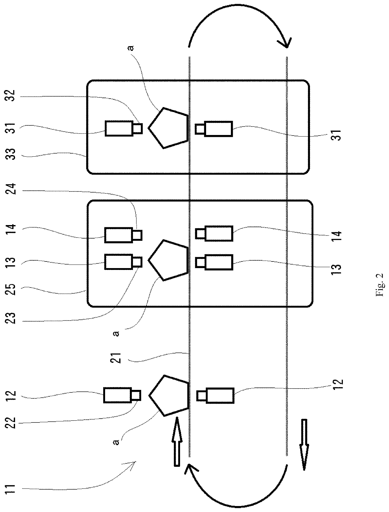
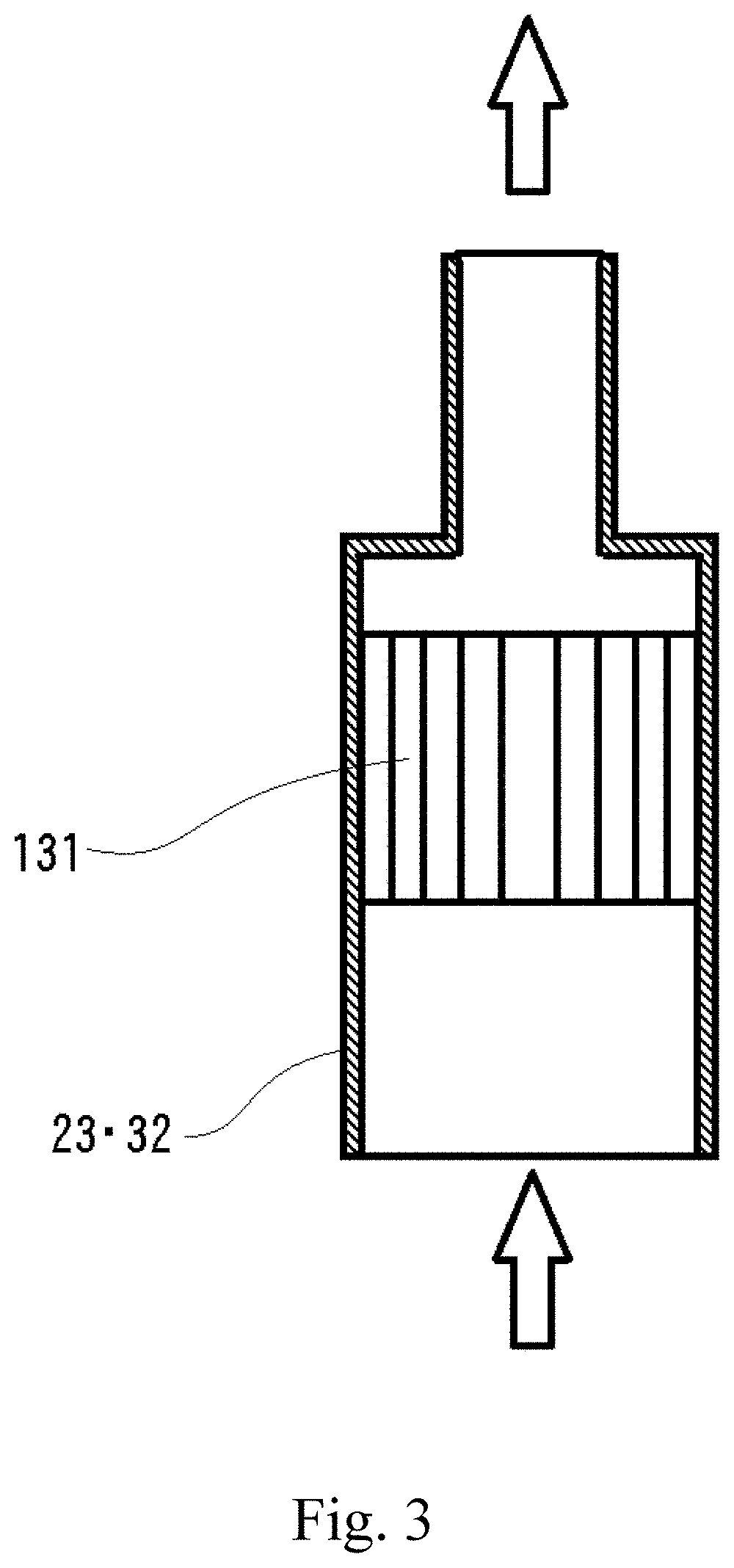
[0048]First, an oil removal system according to an embodiment of the present invention will be described on basis of FIGS. 1 to 3.

[0049](Outline of Oil Removal System)

[0050]The oil removal system provides an oil removal device 11 to remove oil of an object to be treated a using a superheated steam b and a superheated steam generation device 51 to supply the superheated steam b to the oil removal device 11. The oil removal device 11 is used for removing the oil on the surface of the object to be treated a in a post-process of a processing equipment (not shown).

[0051]It is advantageous for production costs to arrange the processing equipment (not shown) and the oil removal device 11 on the same line as a so-called in-line system for continuous processing but they may be arranged in different lines.

[0052](Processing Equipment and Object to be Treated)

[0053]A wide variety of the processing equipment (not shown) can be employed in accordance with a type of the object to be treated a. As ...


PUM

PropertyMeasurementUnit
surface temperature taaaaaaaaaaa
temperatureaaaaaaaaaa
surface temperature taaaaaaaaaaa

Abstract

Provided are an oil removal system and an oil removal method with which good oil removal can be achieved, and a superheated steam generation device which can be used in the execution thereof. An oil removal device imparts, from a discharge part, superheated steam obtained by a superheated steam generation device to a treatment object, which includes oil on the surface thereof. The treatment object is set so that the surface temperature thereof is cooled by a cooling part so as to be lower than the superheated steam. Dew condensation is produced on the surface of treatment object by the discharge of the superheated steam from the discharge part, and the dew condensation is blown off and removed from the surface of the treatment object by a removal part, and thereby oil on the surface is removed together with the dew condensation.

Description

TECHNICAL FIELD[0001]The present invention relates to an oil removal system using superheated steam and a superheated steam generation device.BACKGROUND ART[0002]As a system for removing an oil adhering to a surface of an object to be treated such as a metal work by using superheated steam, those illustrated in Patent Documents 1 to 5 are known.[0003]Patent Document 1 discloses an oil removal system including a washing water nozzle which injects spray water from a spray-water nozzle onto a substrate immediately below saturated or superheated steam injection from a steam nozzle, peels / washes by steam explosion due to instantaneous evaporation of sprayed particles, thereby discharging / transporting peeled-off objects.[0004]Therefore, in this system, the superheated steam was used for incurring steam explosion due to contact with water to peel / wash and was not used to remove an oil by dew condensation.[0005]Patent Documents 2 and 3 disclose an oil removal system in which, for example, a...

Claims


Application Information

Patent Timeline
Patent Type & Authority Applications(United States)
IPC IPC(8): B21B45/02B08B3/10C23G5/00
CPCC23G5/00B08B3/106B21B45/0284B08B3/022B08B5/023B08B2230/01
Inventor TAKEMOTO, TOSHIHIKOTOKAI, TAKAHIROFUKUDA, TAKUMA
Owner MOLITEC STEEL
Why Eureka
Try Eureka