
Panel polishing apparatuses and a panel polishing method

a technology for polishing apparatuses and panels, applied in the direction of grinding feeders, grinding machine components, manufacturing tools, etc., can solve the problems of bottlenecks affecting the production efficiency of panels, low work efficiency, and risk of blocking, so as to improve the polishing efficiency

Inactive Publication Date: 2019-12-19
WUHAN CHINA STAR OPTOELECTRONICS TECH CO LTD
View PDF0 Cites 2 Cited by
  • Summary
  • Abstract
  • Description
  • Claims
  • Application Information

AI Technical Summary

Benefits of technology

The present invention is a panel polishing apparatus and method that can improve efficiency. It can polish multiple panels simultaneously, which reduces the time between panels and increases the polishing speed. This also avoids the risk of blockage in the buffer panel. Overall, this invention makes the polishing process faster and more efficient.

Problems solved by technology

The work efficiency is low, which becomes a bottleneck affecting panel production efficiency.
Due to the inefficiency of the chamfer polishing leads to the accumulation of the diced panels in the buffer zone, which easily leads to the risk of blocking.
Therefore, how to improve the production efficiency of the polishing machine becomes an urgent problem to be solved.

Method used


Image

  • Panel polishing apparatuses and a panel polishing method
  • Panel polishing apparatuses and a panel polishing method
  • Panel polishing apparatuses and a panel polishing method

Examples


Embodiment Construction

[0027]In order to make the purpose, technical solutions and advantages of the present invention more comprehensible, the present invention is further described in detail below with reference to the accompanying drawings and embodiments. It should be understood that the specific embodiments described herein are only used to explain the present invention, and are not intended to limit the present invention.

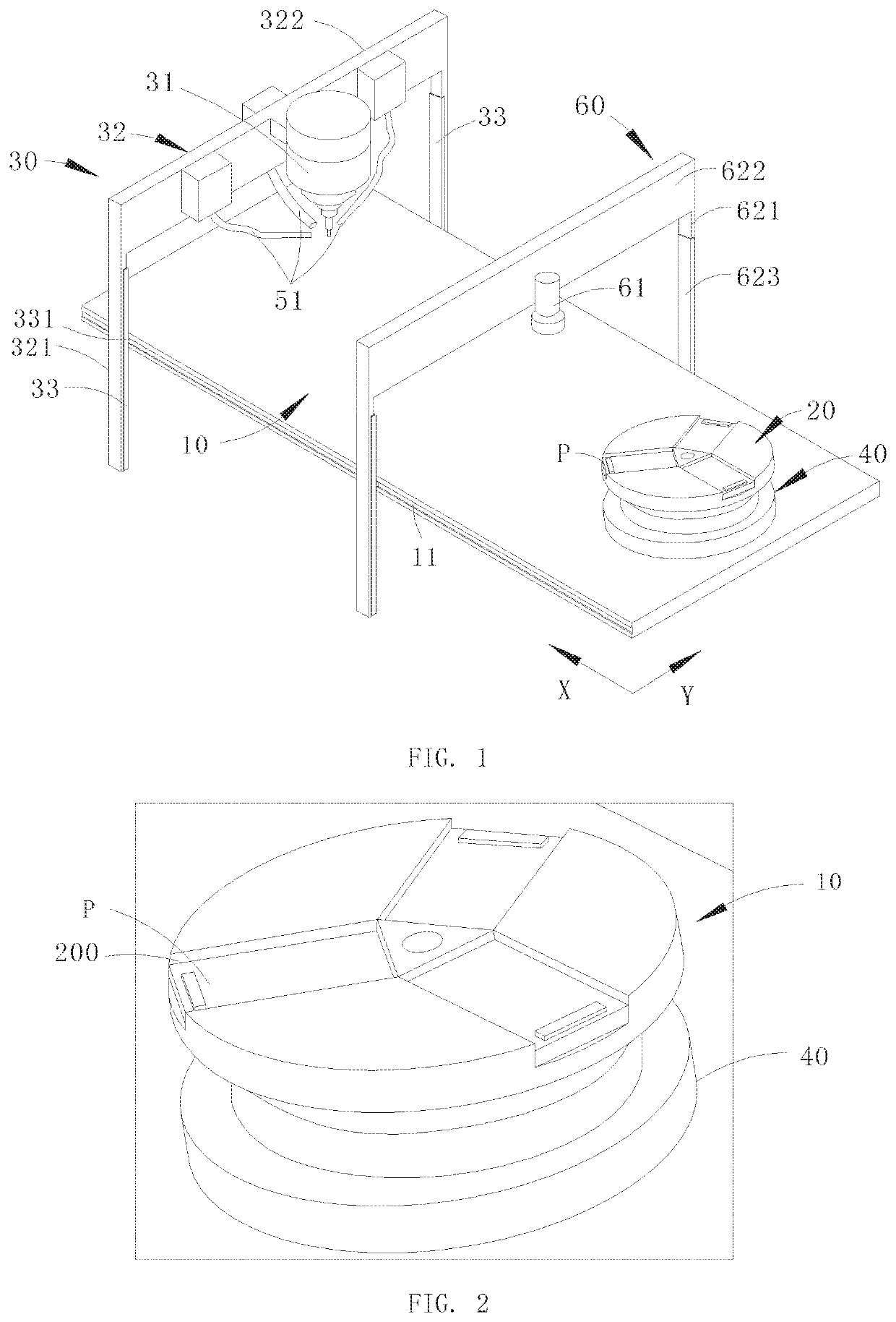
[0028]Referring to FIG. 1 and FIG. 2, the polishing apparatus for a panel in the present embodiment comprises a carrier 10, a disk 20 which is rotatably arranged on a top surface of the carrier 10, and a polishing mechanism 30. A plurality of trenches 200 are located on the disk for placing the panel P, and the polishing mechanism 30 is used for polishing the panel P disposed in the trench 200.

[0029]As shown in FIG. 3, as an exemplary driving manner, a rotation motor 40 is fixed on the carrier 10 in the present embodiment. A base of the rotation motor 40 is fixed on the carrier 10. ...


PUM


Abstract

The present invention provides a polishing apparatus for a panel which comprise a carrier, a disk which is rotatably arranged on a top surface of the carrier and a polishing mechanism. A plurality of trenches is located on the disk, and the polishing mechanism is used for polishing the panel disposed in the trench. The present invention further provides a method for polishing a panel. The present invention can polish batches of batches at one time. During the polishing process, the current panel is polished, and just turn the turntable to a suitable position to switch to the next panel to continue the grind process and repeat the process until all the panel polishing is completed. It reduces the polishing pause time between multiple panels and improves the polishing speed. It also avoids the blocking risk of the buffer panel zone.

Description

RELATED APPLICATIONS[0001]The present application is a National Phase of International Application Number PCT / CN2017 / 113245, filed Nov. 28, 2017, and claims the priority of China Application 201711160755.8, filed Nov. 20, 2017.BACKGROUND OF THE INVENTION1. Field of the Invention[0002]The present invention relates to the field of display panel processing technology, and in particular to a panel polishing apparatus and a panel polishing method.2. The Related Arts[0003]Generally, in the panel industry, in order to prevent the circuit from cutting by the glass edge of the liquid crystal display module or to remove the Lateral Crack, the Median Crack, and the avoidance of the person taking a piece of the glass surface of the liquid crystal display module and then sharp cut by the glass, the panel needs polishing process.[0004]At present, chamfering polishing machines mostly require manual sheeting and pick-up. The carrying panel of the bearing panel adopts a single-body design, and only ...

Claims


Application Information

Patent Timeline
IPC IPC(8): B24B9/10B24B41/00B24B41/06B24B55/06
CPCB24B55/06B24B41/005B24B9/10B24B41/068B24B27/0069B24B41/06B24B45/003B24B55/00
Inventor HUANG, JIANLONG
Owner WUHAN CHINA STAR OPTOELECTRONICS TECH CO LTD
Learn More