Pressure detection device

Active Publication Date: 2019-12-05
HITACHI ASTEMO LTD
View PDF0 Cites 0 Cited by
  • Summary
  • Abstract
  • Description
  • Claims
  • Application Information

AI Technical Summary

Benefits of technology

The invention improves the ability of a pressure sensor to resist noise without using a specific type of metal bonding.

Problems solved by technology

At this time, if the noises flow into a processing circuit on its way, the processing circuit may cause a malfunction.

Method used


Image

  • Pressure detection device
  • Pressure detection device
  • Pressure detection device

Examples


Embodiment Construction

[0016]Hereinafter, embodiments of the invention will be described.

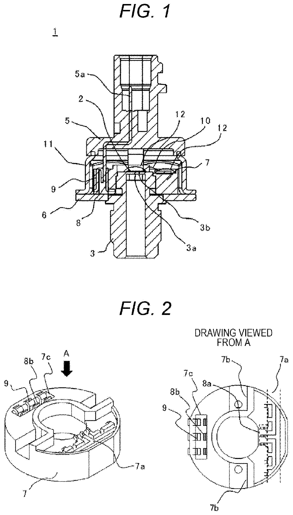
[0017]FIG. 1 is a vertical cross-sectional view illustrating a configuration of a pressure detection device 1 according to an embodiment of the invention. The pressure detection device 1 is mounted in a vehicle, and includes a sensor element 2, a pressure port 3, a connector subassembly 5, a base member 6, a connection member 7, a lead frame 8, and a pressing terminal 9.

[0018]In the upper portion of the pressure port 3, there is provided a rectangular diaphragm 3a which operates as a pressure-receiving surface of a pressure medium to be measured. The upper surface of the diaphragm 3a, that is, a surface opposite to the pressure-receiving surface, serves as a pedestal surface 3b where the sensor element 2 is placed. The pressure port 3 guides the pressure medium such as a working fluid and a liquid fuel to the pressure-receiving surface of the diaphragm 3a. With this configuration, the diaphragm 3a is deformed accordin...


PUM


Abstract

A noise resistance of a pressure sensor is improved while avoiding a hetero metal bonding. A pressure detection device includes a metal case having the diaphragm which is deformed due to a pressure received from a pressure medium, a sensor element which detects a pressure by detecting the deformation of the diaphragm, a lead frame which is electrically connected to the sensor element, and a connection member which holds the lead frame. A first surface of the lead frame, that is, the surface on a side near the metal case in the parallel plate region, and a second surface of the metal case, that is, the upper surface of the base member interpose at least one of the resin of the connection member being an insulator and the insulating adhesive and are disposed to face each other with a predetermined gap therebetween.

Description

TECHNICAL FIELD[0001]The present invention relates to a pressure detection device.BACKGROUND ART[0002]To achieve environmental friendliness of a vehicle and to improve fuel consumption, a hydraulic system for generating oil pressure by an electric motor, a fuel injection system for injecting fuel by applying pressure to the fuel, and other systems are increasingly adopted. These systems include pressure sensors to detect pressure. In general, a pressure sensor is stored in a metal case to ensure strength reliability, and is attached, by screws, to a metal pipe through which a pressure medium as a measurement target, such as a working fluid, and a liquid fuel. The metal pipe is fixed to a structure at a body GND potential such as the body or the engine of the vehicle. Therefore, the potential of the metal case of the pressure sensor becomes the body GND potential similarly to the metal pipe.[0003]The pressure sensor is connected to an electronic control unit (ECU) mounted in the vehi...

Claims


Application Information

Patent Timeline
IPC IPC(8): G01L19/00G01L19/14G01L19/06
CPCG01L19/141G01L19/148G01L19/069G01L19/0061G01L9/0051G01L19/0084G01L19/142
Inventor TERADA, DAISUKEONUKI, HIROSHIAOYAGI, TAKUYA
Owner HITACHI ASTEMO LTD
Why Eureka
Try Eureka