Control device

A control device and housing technology, applied in the directions of clamping/extracting device, support structure installation, circuit layout on support structure, etc., can solve problems such as increased cost and large energy waste, and achieve increased degree of freedom and stable products. Improved performance and noise resistance

Active Publication Date: 2017-06-27
YAMATAKE HONEYWELL CO LTD
View PDF6 Cites 3 Cited by
  • Summary
  • Abstract
  • Description
  • Claims
  • Application Information

AI Technical Summary

Problems solved by technology

In addition, even if the customer needs fewer functions, since the configuration of each column is predetermined, the configuration exceeds the functions required by the customer, and there are problems such as increased cost and large energy waste.

Method used


Image

  • Control device
  • Control device
  • Control device

Examples


Embodiment Construction

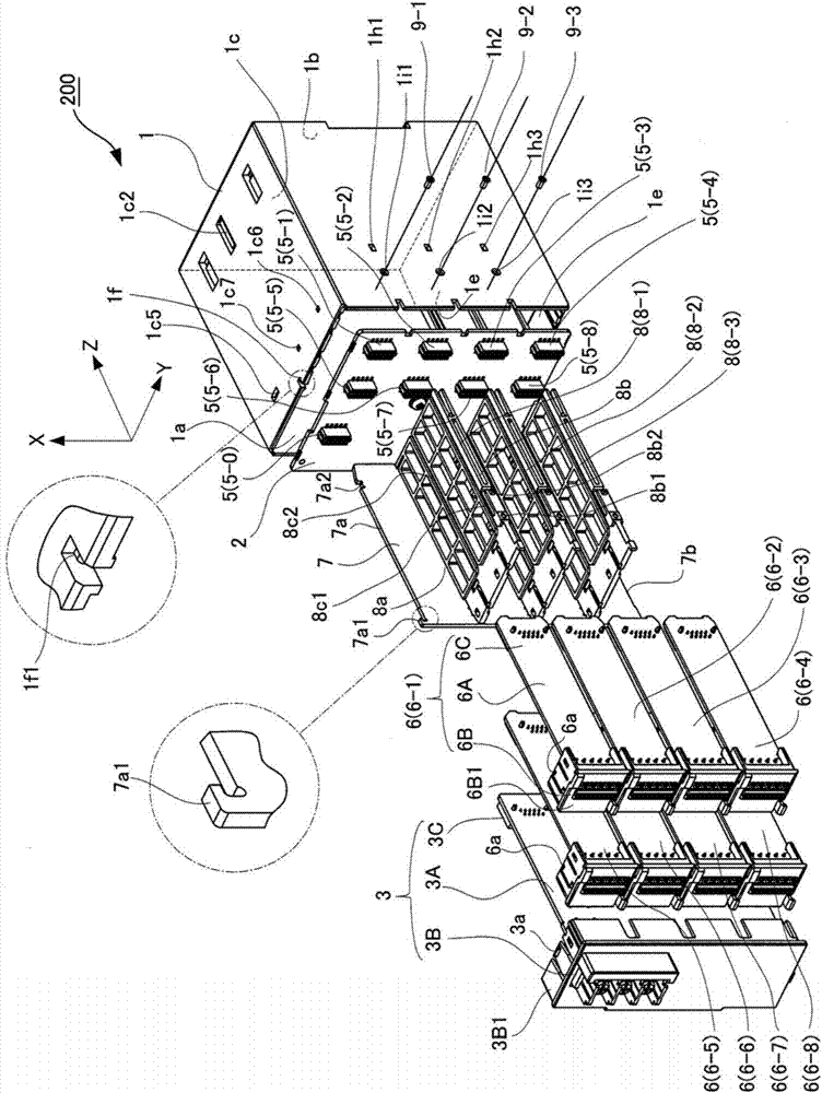
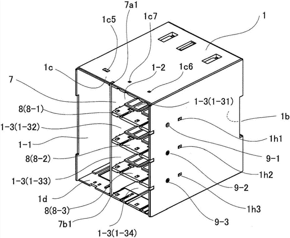
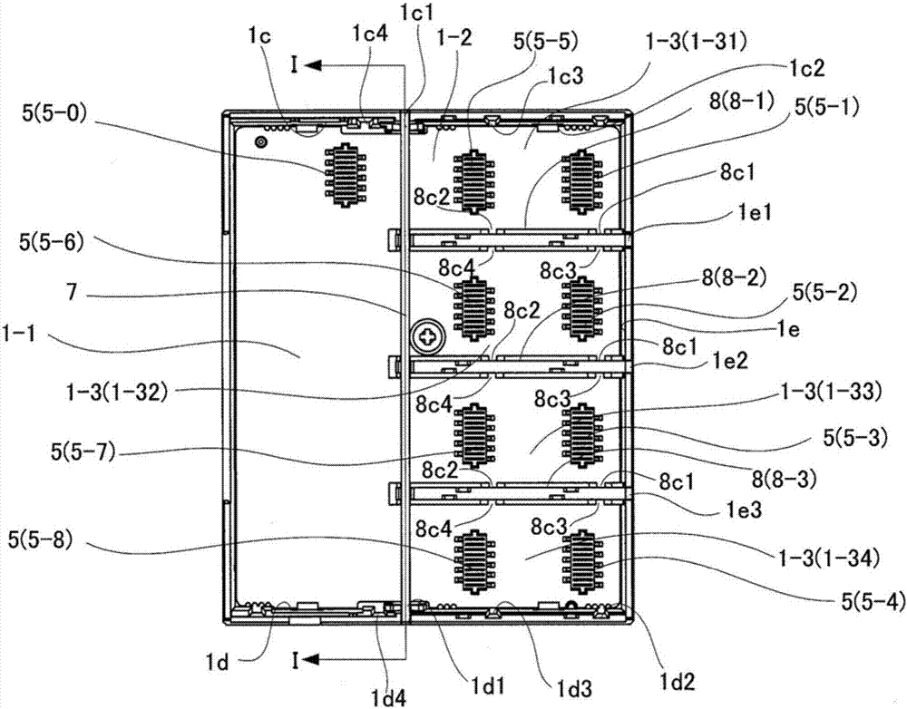
[0040] Hereinafter, embodiments of the present invention will be described in detail with reference to the drawings. figure 1 It is an exploded perspective view showing main parts of the control device according to the embodiment of the present invention. In this figure, with Figure 14 The same notation is indicated with the reference Figure 14 The description of the constituent elements that are the same as or equivalent to the constituent elements described above is omitted.

[0041] This control device 200 is the same as the conventional control device 100 in that it includes a casing 1 made of a resin member with an opening 1 a on the front, a motherboard 2 installed in the casing 1 , and an electrical connection with the motherboard 2 . The main unit 3, but the difference lies in the installation structure of the functional blocks in the housing 1. Hereinafter, the functional blocks used in this embodiment are denoted by reference numeral 6 to distinguish them from th...


PUM


Abstract

The invention provides a control device, wherein the maintenance is improved, the cost is reduced, the energy is saved, and the space is saved. 1It is possible to combine several functions in a column. The space in the case 1 is partitioned into the partial spaces 1-1 and 1-2 in the lateral direction by the first partition plate (partition plate (vertical)) 7. The partial space 1-2 in the transverse direction is divided into partial spaces 1-31 and 1-32 in the vertical direction by the second partition plates (partition plates (horizontal)) 8-1, 8-2 and 8-3. , 1-33, 1-34). And the functional blocks 6-1 to 6-8 are mounted on the divided partial spaces 1-31, 1-32, 1-33, 1-34.

Description

technical field [0001] The present invention relates to a control device that imports data from an input device to control the action of an output device. Background technique [0002] Conventionally, control devices that control temperature, humidity, pressure, flow rate, etc. in a process have been used as control devices that import data from input devices to control operations of output devices. The control device includes a case with an opening on the front, a motherboard provided in the case, and functional blocks electrically connected to the motherboard (for example, refer to Patent Document 1). [0003] Figure 14 The structure of the main part of the conventional control device is shown. The control device 100 includes a case 1 made of a resin member with an opening 1 a on the front, a motherboard 2 installed in the case 1 , and a main unit 3 and a function block 4 electrically connected to the motherboard 2 . In this example, two functional blocks 4 - 1 and 4 - ...

Claims


Application Information

Patent Timeline
Patent Type & Authority Applications(China)
IPC IPC(8): H05K7/02H05K7/14
CPCH05K7/023H05K7/1411G06F1/183H05K7/1424H05K7/1439H05K7/1449
Inventor 内海庆也藤川刚生
Owner YAMATAKE HONEYWELL CO LTD
Why Eureka
Try Eureka