
Amplifying circuit, reception circuit, and semiconductor integrated circuit

A technology for amplifying circuits and input circuits, applied to amplifiers with semiconductor devices/discharge tubes, improved amplifiers to reduce temperature/power supply voltage changes, amplifiers, etc., can solve problems such as the influence of variable resistor resistance values, and achieve improved noise The effect of patience

Active Publication Date: 2018-11-09
SOCIONEXT INC
View PDF18 Cites 0 Cited by
  • Summary
  • Abstract
  • Description
  • Claims
  • Application Information

AI Technical Summary

Problems solved by technology

Therefore, the resistance value of the variable resistor is easily affected by noise, etc.

Method used


Image

  • Amplifying circuit, reception circuit, and semiconductor integrated circuit
  • Amplifying circuit, reception circuit, and semiconductor integrated circuit
  • Amplifying circuit, reception circuit, and semiconductor integrated circuit

Examples


Embodiment Construction

[0025] Embodiments of the present invention will be described below based on the drawings.

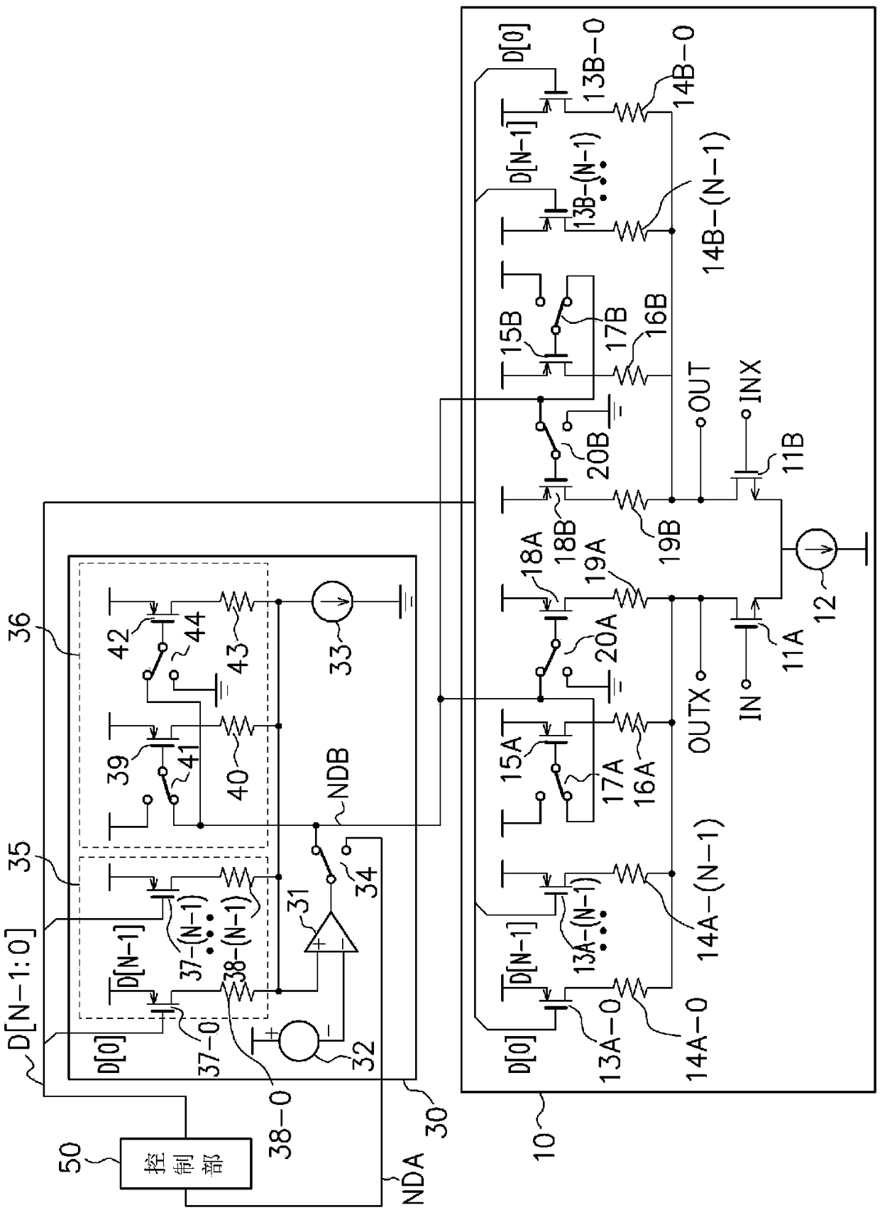
[0026] figure 1 It is a diagram showing a configuration example of an amplifier circuit in one embodiment of the present invention. The amplifier circuit in this embodiment includes an amplifier unit 10 , a correction circuit unit 30 , and a control unit 50 . The amplifying unit 10 has an input circuit unit that receives an input signal, and a load circuit unit that is used as a load and is composed of a variable resistance circuit controlled to a desired resistance value, and amplifies a differential input with a specific gain (magnification). signal and output.

[0027] In the amplifier unit 10 , the NMOS transistors 11A and 11B included in the input circuit unit form drive elements in the differential amplifier unit. The gate of NMOS transistor 11A is connected to input terminal IN to which one signal of a differential input signal is input, and the source is connected to curren...


PUM


Abstract

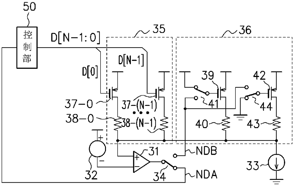
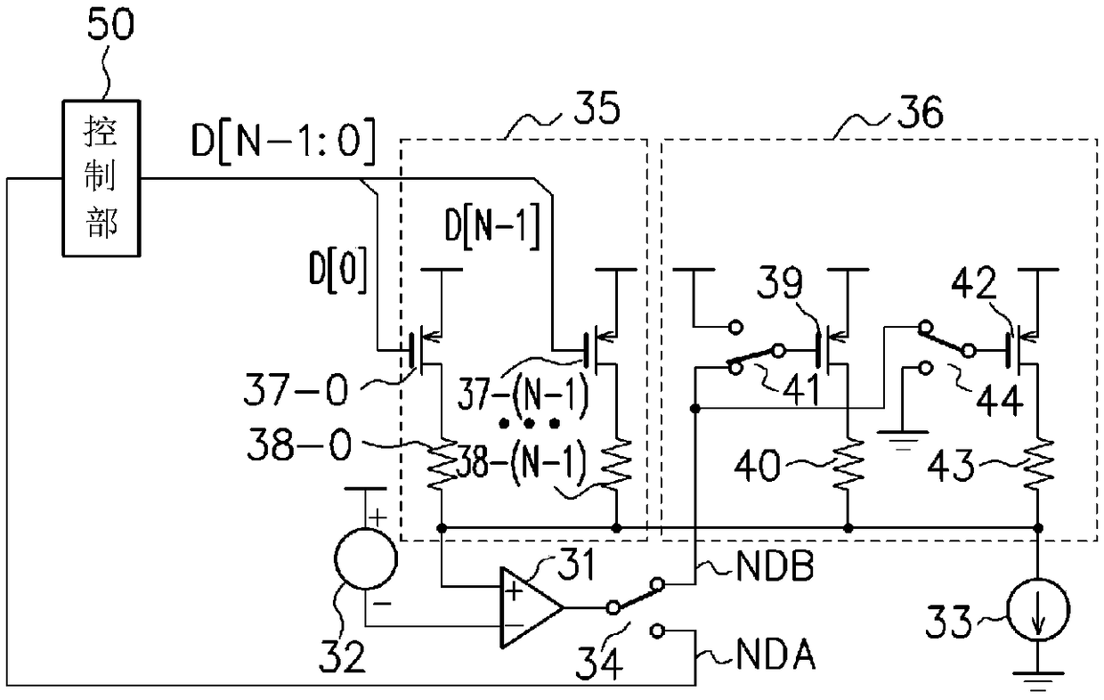
An amplifying circuit of the present invention is provided with: an input circuit unit (10) that receives an input signal; a load circuit unit (10), which is provided in series with the input circuitunit, and which has a first variable resistance unit, in which a resistance value is controlled by means of a digital code, and a second variable resistance unit, in which a resistance value is controlled by means of an analog control voltage; and a correction circuit unit (30) for correcting a resistance value of the load circuit unit, said correction circuit unit having a third variable resistance unit (35), which has a circuit configuration corresponding to the first variable resistance unit, and in which a resistance value is controlled by means of the digital code, and a fourth variable resistance unit (36), which has a circuit configuration corresponding to the second variable resistance unit, and in which a resistance value is controlled by means of the analog control voltage. The amplifying circuit makes it possible to roughly regulate the resistance value by means of the control using the digital code, and to finely regulate the resistance value by means of the control using the analog control voltage.

Description

technical field [0001] The present invention relates to an amplifier circuit, a receiver circuit and a semiconductor integrated circuit. Background technique [0002] In analog signal processing, resistive elements are widely used as elements for converting current signals into voltage signals. In such a circuit, the resistance value of the resistance element affects circuit characteristics such as the gain of the amplifier circuit and the cutoff frequency of the filter circuit, for example. In general, the resistance value of a resistance element formed by a semiconductor process varies within a certain range, or the resistance value may depend on ambient temperature. [0003] For example, in order to keep the gain of an amplifying circuit with a resistive load constant, it is necessary to correct the deviation and fluctuation of the resistance value of the resistive load so as to maintain it at a constant value. As one method of correcting variations and fluctuations in ...

Claims


Application Information

Patent Timeline
IPC IPC(8): H03F3/45H03F1/30
CPCH03F3/45766H03F3/45771H03G1/0088H03G3/30H03F2200/453H03F2203/45624H03F2203/45726H03G1/0029H03G3/001H03F3/45183H03F2200/447H03F1/304H03F1/30H03F2203/45208H03K5/24
Inventor 工藤真大
Owner SOCIONEXT INC
Learn More