Elevator control device

A technology of elevator control device and speed control device, which is applied in the direction of AC motor control, control system, vector control system, etc., can solve problems such as power converter capacity constraints, and achieve improved noise resistance, increased freedom, and simple wiring Effect

Active Publication Date: 2015-02-04
MITSUBISHI ELECTRIC CORP
View PDF5 Cites 0 Cited by
  • Summary
  • Abstract
  • Description
  • Claims
  • Application Information

AI Technical Summary

Problems solved by technology

[0004] However, in a transistor converter or a transistor inverter used in a power converter, the maximum capacity that can be handled as an element is predetermined, and the capacity of the power converter is restricted by the capacity of the element

Method used


Image

  • Elevator control device
  • Elevator control device
  • Elevator control device

Examples


Embodiment approach 1

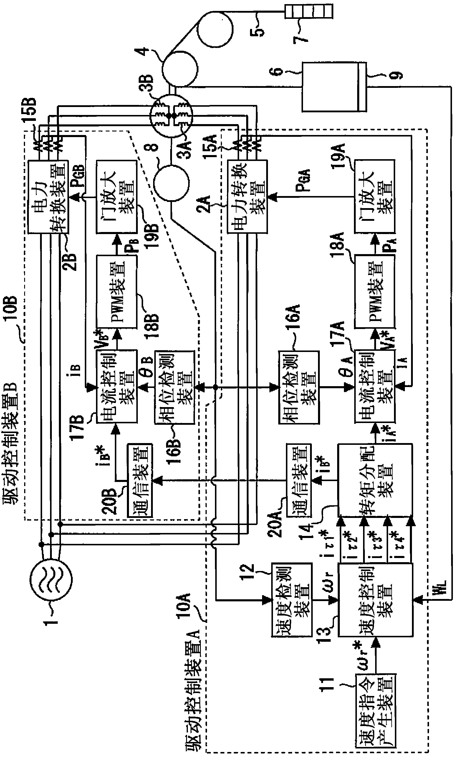
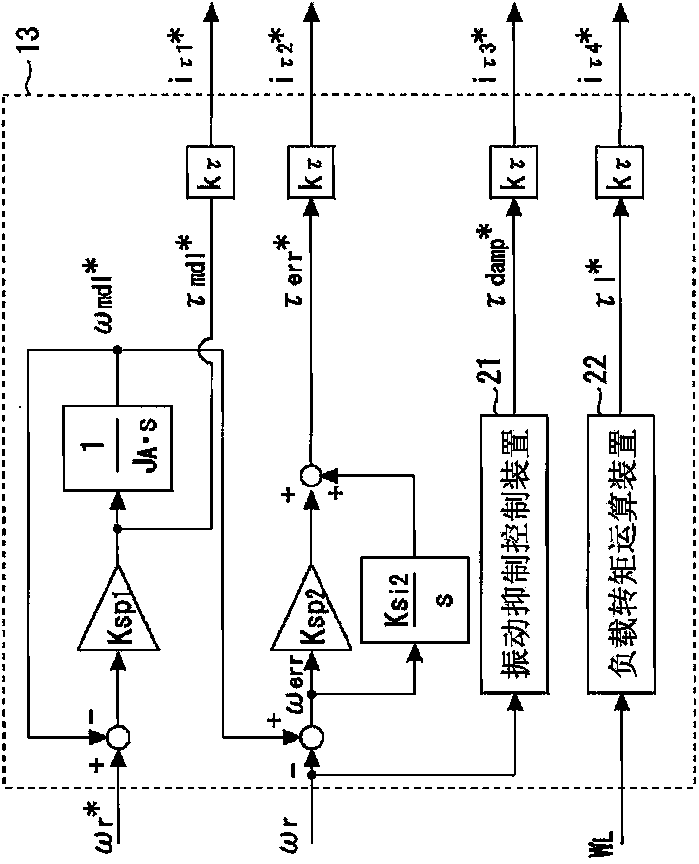
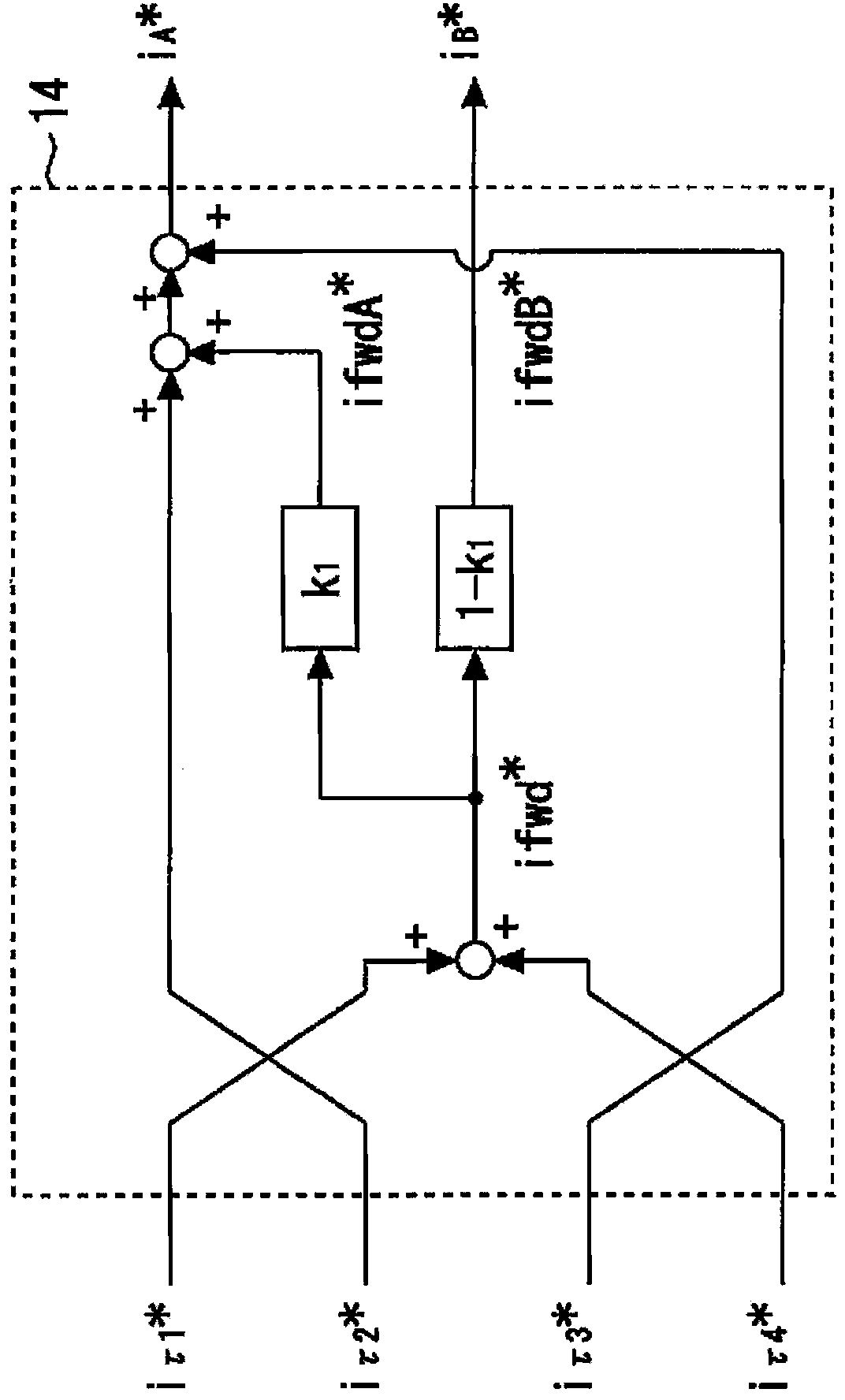
[0027] Figure 1 ~ Figure 3 Regarding Embodiment 1 of the present invention, figure 1 is a system configuration diagram showing the overall configuration of the elevator control device, figure 2 is an explanatory diagram showing the internal structure of the speed control device, image 3 It is an explanatory diagram showing the internal structure of the torque distribution device.

[0028] In the figure, 1 is a commercial power supply which is a three-phase AC power supply for supplying electric power to the elevator. The three-phase AC power from the commercial power supply 1 is input to the first power conversion device 2A and the second power conversion device 2B respectively, and the voltage and frequency are respectively converted in the first power conversion device 2A and the second power conversion device 2B. Variable voltage and variable frequency alternating current are output separately.

[0029] The AC power output from the first power conversion device 2A is...


PUM


Abstract

Provided is a multi-drive elevator control device which can shorten gate signal lines between a gate amplifier and each power converter and is capable of improving the noise immunity in gate signals. For this purpose, an elevator control device having two or more driving controllers, a motor which drives an elevator by being controlled by each of the driving controllers, and a power converter which is provided in each of the driving controllers and supplies power to the motors comprises: a speed controller which is provided in one of the driving controllers and outputs a torque command on the basis of a speed command; a torque distributor which is provided in the one driving controller and distributes the torque command to a distributed torque command of each of the driving controllers; and a communication device which transmits the distributed torque command to the other riving controller. In this elevator control device, the power converter provided in the other driving controller supplies power to the motor in accordance with the distributed torque command transmitted by the communication device.

Description

technical field [0001] The present invention relates to elevator controls. Background technique [0002] Generally, an elevator has, as its drive system, a drive system consisting of a motor for driving a car, a power converter paired with the motor, and a control device for the power converter. And, in this case, the required capacity of the motor is mainly determined according to the speed of the elevator and the carrying capacity of the car. The higher the speed and the greater the carrying capacity, the greater the required capacity of the motor. [0003] Therefore, a drive device corresponding to a so-called high-speed or ultra-high-speed elevator requires a drive system composed of a large-capacity electric motor and a large-capacity power converter paired with the electric motor. [0004] However, in a transistor converter or a transistor inverter used in a power converter, the maximum capacity that can be handled as an element is predetermined, and the capacity of t...

Claims


Application Information

Patent Timeline
Patent Type & Authority Patents(China)
IPC IPC(8): H02P5/46B66B1/30
CPCH02P21/06B66B1/30H02P5/46H02P25/22
Inventor 平林一文
Owner MITSUBISHI ELECTRIC CORP
Why Eureka
Try Eureka