
Apparatus and method for wireless communication

a wireless communication and apparatus technology, applied in electrical apparatus, digital transmission, transmission path sub-channel allocation, etc., can solve the problems of inability to effectively distinguish pilot signals, limited system performance of large-scale mimo system, and lack of orthogonal pilots, so as to improve the utilization efficiency of pilot sequences and reduce pilot pollution. , the effect of enhancing the accuracy of uplink channel estimation

Active Publication Date: 2019-11-07
SONY CORP
View PDF4 Cites 0 Cited by
  • Summary
  • Abstract
  • Description
  • Claims
  • Application Information

AI Technical Summary

Benefits of technology

This patent is about a way to improve communication between devices by using pilot sequences. By sharing pilot sequences, the devices can avoid interference and improve the accuracy of channel estimation and pre-coding, which results in better communication quality. Overall, this improves the overall performance of the system.

Problems solved by technology

However, the system performance of the large-scale MIMO system is limited by pilot pollution problem in a scenario of, for example, multi-cell time-division multiplexing.
Specifically, since the length of the pilot is limited by a coherence length of a channel, the number of orthogonal pilots is limited, and the pilots may be inevitably shared among different cells.
In this case, pilot signals transmitted by user equipments in different cells using the same pilot sequence may be received by a base station in a neighboring cell, which, however, cannot effectively distinguish the pilot signals from each other, thereby resulting in interferences to uplink channel estimation at the base station.
When performing uplink data detection using the interfered channel estimation, the base station may receive data from user equipments in other cells, besides data transmitted by user equipments in the cell where the base station is located, thereby resulting in inter-cell interferences in the uplink.
When the base station generates a pre-coding matrix and transmits downlink data using the interfered channel estimation, besides the user equipments in the cell where the base station is located, user equipments in other cells may also receive the data, thereby resulting in inter-cell interferences in the downlink.
Theoretical studies have demonstrated that, although both spectral efficiency and energy efficiency of the large-scale MIMO system can be significantly improved, and the influences of noises and channel estimation error on the system performance are reduced as the number of antennas of the base station is increased, the inter-cell interferences caused by the pilot pollution cannot be eliminated and become one of the factors limiting the performance of the large-scale MIMO system.
In addition, conventional methods for alleviating the pilot pollution are often difficult to be adapted to current technical conditions.
Therefore, in actual applications, the pilot pollution is still one of the most serious problems confronted by the large-scale MIMO system.

Method used


Image

  • Apparatus and method for wireless communication
  • Apparatus and method for wireless communication
  • Apparatus and method for wireless communication

Examples


first embodiment

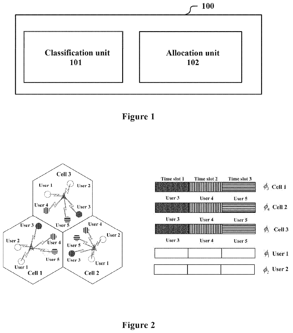
[0033]FIG. 1 illustrates a block diagram of a structure of an apparatus 100 for wireless communications according to an embodiment of the present disclosure. The apparatus 100 includes: a classification unit 101, configured to classify communication devices in a cell where the apparatus 100 is located into a plurality of communication device groups, wherein the plurality of communication device groups include a first communication device group and a second communication device group, and an allocation unit 102, configured to allocate pilot sequences in a first pilot group to the first communication device group, and allocate pilot sequences in a second pilot group to the second communication device group, wherein at least one of the following reuse configurations is performed in the case that the pilot sequences are insufficient: at least part of the communication devices in the second communication device group reuse at least one of the pilot sequences in the second pilot group, an...

second embodiment

[0068]FIG. 12 illustrates a block diagram of an apparatus 200 for wireless communications according to another embodiment of the present disclosure. Besides the units shown in FIG. 1, the apparatus 200 further includes a notification unit 201 configured to notify a corresponding communication device of information on the allocated pilot sequence and time resource.

[0069]The information may be contained in, for example, at least one of PDCCH signaling and RRC signaling.

[0070]For example, the transmission period and the subframe offset of the pilot sequence may be configured using the RRC signaling. Communication devices involved in the reusing have different subframe offsets. As described above, the allocation unit 102 may select, according to the cell ID, an edge pilot sequence which takes a cyclic shift as the index. The apparatus 200 may further include a signaling generation unit (not shown in FIG. 12), which is configured to generate the RRC signaling which includes the transmiss...

third embodiment

[0074]As described in the first embodiment, the classification unit 101 classifies communication devices on the cell edge to the second communication device group. In this embodiment, the classification unit may be configured to perform the classification according to channel conditions of the communication device. For example, a communication device with good channel conditions is classified into the first communication device group, and a communication device with poor channel conditions is classified into the second communication device group.

[0075]As shown in FIG. 13, besides the units in the apparatus 100, the apparatus 300 for wireless communications according to this embodiment further includes a reception unit 301 configured to receive channel quality measurement information and / or a radio resource management measurement report from the communication device. The channel quality measurement information and / or the radio resource management measurement report are used by the cl...


PUM


Abstract

An apparatus for wireless communication includes a classification unit and an allocation unit. The classification unit classifies communication devices in a cell where the apparatus is located, the communication devices are classified into a plurality of communication device groups including a first communication device group and a second communication device group. The allocation unit allocates pilot frequency sequences in a first pilot frequency group to the first communication device group, and allocates pilot frequency sequences in a second pilot frequency group to the second communication device group. When the number of the pilot frequency sequences is insufficient, a multiplexing configuration is executed, such as communication devices in the second communication device group multiplex at least one pilot frequency sequence in the second pilot frequency group.

Description

CROSS-REFERENCE TO RELATED APPLICATIONS[0001]This application is a continuation of U.S. application Ser. No. 15 / 543,416, filed Jul. 13, 2017, which is based on PCT filing PCT / CN2016 / 072277, filed Jan. 27, 2016, and claims priority to CN 201510079631.1, filed Feb. 13, 2015, the entire contents of each are incorporated herein by reference.FIELD OF THE INVENTION[0002]The embodiments of the present disclosure generally relate to the technical field of wireless communications, and in particular to an apparatus and a method for wireless communications. More specifically, the embodiments of the present disclosure relate to a pilot allocation technology in a large-scale Multiple-Input Multiple-Output (MIMO) communication system.BACKGROUND OF THE INVENTION[0003]Large scale MIMO systems have been widely focused by both the academia and the industry in recent years. Theoretical studies have demonstrated that, both spectral efficiency and energy efficiency of the large-scale MIMO system can be ...

Claims


Application Information

Patent Timeline
Patent Type & Authority Applications(United States)
IPC IPC(8): H04L5/00
CPCH04W72/0446H04L5/0069H04L5/0048
Inventor ZHU, XUDONGWANG, ZHAOCHENGCHEN, JINHUI
Owner SONY CORP
Learn More