Stator for an axial flux machine and method for producing the same

a technology of axial flux and stator, which is applied in the manufacture of stator/rotor bodies, magnetic circuit shapes/forms/construction, windings, etc., can solve the problems of increasing the importance of technical difficulties in cooling the machine, and the topology of the solar panel does raise some technical challenges, so as to improve the mechanical stability and improve the cooling capacity. , the effect of good or improving the mechanical stability

Active Publication Date: 2019-09-19
UNIV GENT +1
View PDF0 Cites 10 Cited by
  • Summary
  • Abstract
  • Description
  • Claims
  • Application Information

AI Technical Summary

Benefits of technology

[0015]It is an object of embodiments of the present invention to provide a yokeless stator for an axial flux electrical machine, and an axial flux machine comprising such a yokeless stator, wherein the yokeless stator and the axial flux electrical machine have a structure with good or improved mechanical stability and / or a good or improved cooling capacity, while avoiding that a cooling liquid comes close to or near the stator teeth or stator coils.
[0016]It is also an object of embodiments of the present invention to provide a method of producing such a yokeless stator and a method of producing such an axial flux electrical machine, wherein the method is relatively easy to perform, in particular in terms of accurately positioning the stator teeth in a manner which does not negatively influence mechanical stability and / or cooling capacity or both.

Problems solved by technology

The YASA topology does, however, raise some technical challenges.
The compactness increases the importance of and technical difficulties in cooling the machine.
Furthermore, there is a challenge related to mechanically fixing the discrete stator teeth in the machine with appropriate accuracy and sufficient rigidness.

Method used


Image

  • Stator for an axial flux machine and method for producing the same
  • Stator for an axial flux machine and method for producing the same
  • Stator for an axial flux machine and method for producing the same

Examples


first preferred embodiment

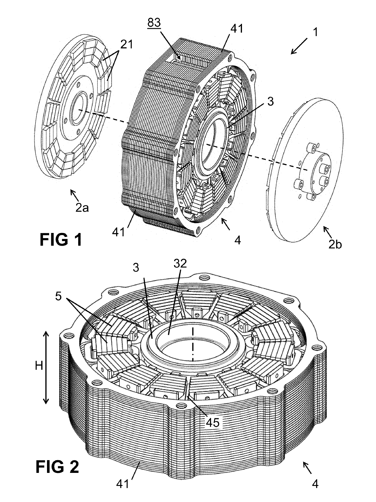
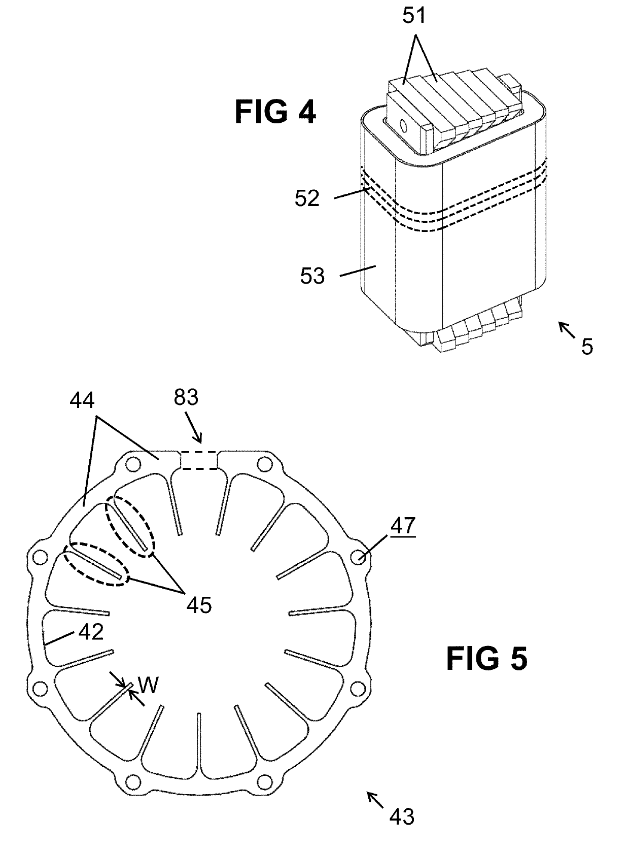
[0115]FIG. 5 shows an example of a lamination 43 or sheet as can be used in embodiments according to the present invention, and FIGS. 6(a) to 6(c) illustrate how such laminations 43 can be stacked on top of each other to form a laminated stack 82 forming the stator housing 41 having a circumferential portion and elongated elements 45 extending radially inwards therefrom. The laminations 43 have a shape comprising a circumferential portion 44 and a plurality of elongated portions 45 extending radially inward from said circumferential portion 44.

[0116]Preferably the laminations 43 are made of a non-ferromagnetic metal or metal alloy, such as copper or aluminium or a copper alloy or an aluminium alloy, because non-ferromagnetic metal or alloys are materials having a relatively low magnetic permeability and a relatively high thermal conductance. This provides low magnetic losses and high heat transport.

[0117]Such laminations 43 can be produced for example by cutting or stamping or punch...

second preferred embodiment

[0137]FIG. 9 and FIG. 10 show another embodiment of a stator 4 according to the present invention in exploded view (FIG. 9) and in assembled form (FIG. 10). The main difference between the embodiment of FIG. 9 and FIG. 10 on the one hand, and the embodiments of FIG. 5 to FIG. 8 on the other hand, is that in the embodiment of FIG. 9 and FIG. 10, the stator 4 comprises a monolithic body 87 having an annular shape forming a circumferential portion of the housing 41. The circumferential portion has a plurality of grooves 49 or slits or the like on an inner surface thereof for mounting a plurality of comb-shaped elements 7, which are separately formed, but mounted to the circumferential portion for example by welding, pressing, soldering or brazing.

[0138]In this embodiment the circumferential portion of the housing 41 is not laminated, but, as mentioned above, that is not of a concern, because the eddy currents are small at the circumferential location. In contrast, the comb-shaped eleme...


PUM

PropertyMeasurementUnit
temperatureaaaaaaaaaa
thicknessaaaaaaaaaa
thicknessaaaaaaaaaa

Abstract

A yokeless stator for an axial flux machine, comprising a housing, the housing comprising a circumferential portion and a plurality of elongated portions extending radially inwards therefrom, and a plurality of discrete stator teeth arranged within the circumferential portion, each discrete stator tooth comprising a ferromagnetic material and an electrical winding; the housing further comprising an electrically isolating filling material filling empty space inside the housing. The circumferential portion of the housing is made of a first non-ferromagnetic material and the elongated portions are made of a second non-ferromagnetic material. The housing comprises a laminated structure, which comprises at least part of the plurality of inwardly directed elongated portions.

Description

FIELD OF THE INVENTION[0001]The invention relates to the field of axial flux electrical machines. More specifically, the present invention relates to a stator for an axial flux electrical machine and to a method of producing the same.BACKGROUND OF THE INVENTION[0002]Many different types of electrical machines (both motors and generators) exist in the prior art, e.g. brushless DC (BLDC) motors / generators, synchronous or asynchronous AC motors / generators, switched reluctance motors / generators (SRM), axial flux (AF) motors / generators, etc., and each type has its specific advantages and disadvantages, e.g. in terms of the physical machine itself, in terms of its driving circuit (e.g. requiring a DSP or a simple microcontroller), in terms of required sensors (e.g. current sensor, position sensor), in terms of characteristics (e.g. torque ripple), etc.[0003]The present invention is concerned with the type of “axial flux machines”, and more in particular, with so called yokeless axial flux...

Claims


Application Information

Patent Timeline
Patent Type & Authority Applications(United States)
IPC IPC(8): H02K9/22H02K1/18
CPCH02K9/22H02K1/182H02K1/14H02K21/24H02K3/522H02K9/227H02K15/14Y10T29/49009H02K15/028H02K15/02Y10T29/49078
Inventor VANSOMPEL, HENDRIKSERGEANT, PETERLEIJNEN, PETER
Owner UNIV GENT
Why Eureka
Try Eureka