Imaging device and camera

Active Publication Date: 2019-09-05
PANASONIC INTELLECTUAL PROPERTY MANAGEMENT CO LTD
View PDF0 Cites 0 Cited by
  • Summary
  • Abstract
  • Description
  • Claims
  • Application Information

AI Technical Summary

Benefits of technology

The patent describes a camera configuration that can achieve the same benefits as an imaging device described earlier. The camera includes an optical system with lenses that focus external light on the camera's imaging element. The optical system has a zoom lens that can change the size of the image, a focus lens that can adjust the focus, and a hand shake correction lens that can cancel out shaking. The camera also has a diaphragm with an aperture section that can adjust the amount of light transmitted. Overall, the camera can capture images with the same beneficial effects of the imaging device described earlier.

Problems solved by technology

However, the multiplication of the digital gain causes a deterioration in bit accuracy of a video signal and an increase in quantization noise along with the deterioration, which leads to a problem that unnecessarily large noise is generated.

Method used


Image

  • Imaging device and camera
  • Imaging device and camera
  • Imaging device and camera

Examples


embodiment 1

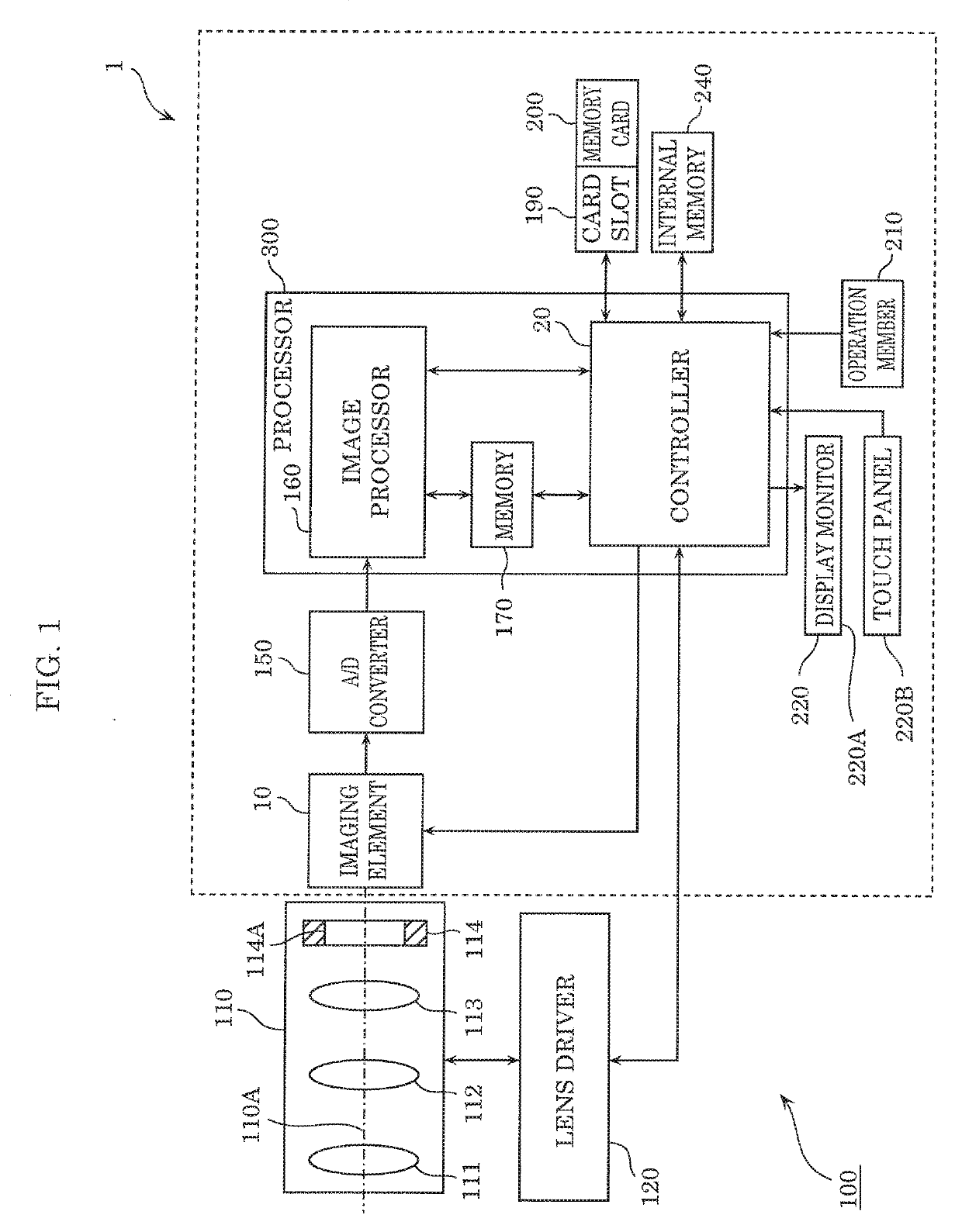
[0032]A configuration and operation of an imaging device according to Embodiment 1 will be described below.

[1. Configuration]

[0033]FIG. 1 is a block diagram illustrating a configuration of camera 100 according to Embodiment 1.

[0034]Camera 100 includes optical system 110, lens driver 120, and imaging device 1.

[0035]Optical system 110 includes one or more lenses that focus external light on imaging element 10 of imaging device 1. Specifically, optical system 110 includes zoom lens 111, hand shake correction lens 112, focus lens 113, and diaphragm 114. Zoom lens 111 is caused to move along optical axis 110A, thereby enabling an object image to be enlarged or reduced. Further, focus lens 113 is caused to move along optical axis 110A, thereby enabling focusing of the object image to be adjusted. Furthermore, hand shake correction lens 112 is movable within a plane perpendicular to optical axis 110A of optical system 110. Hand shake correction lens 112 is moved in a direction in which sha...

modified example 1

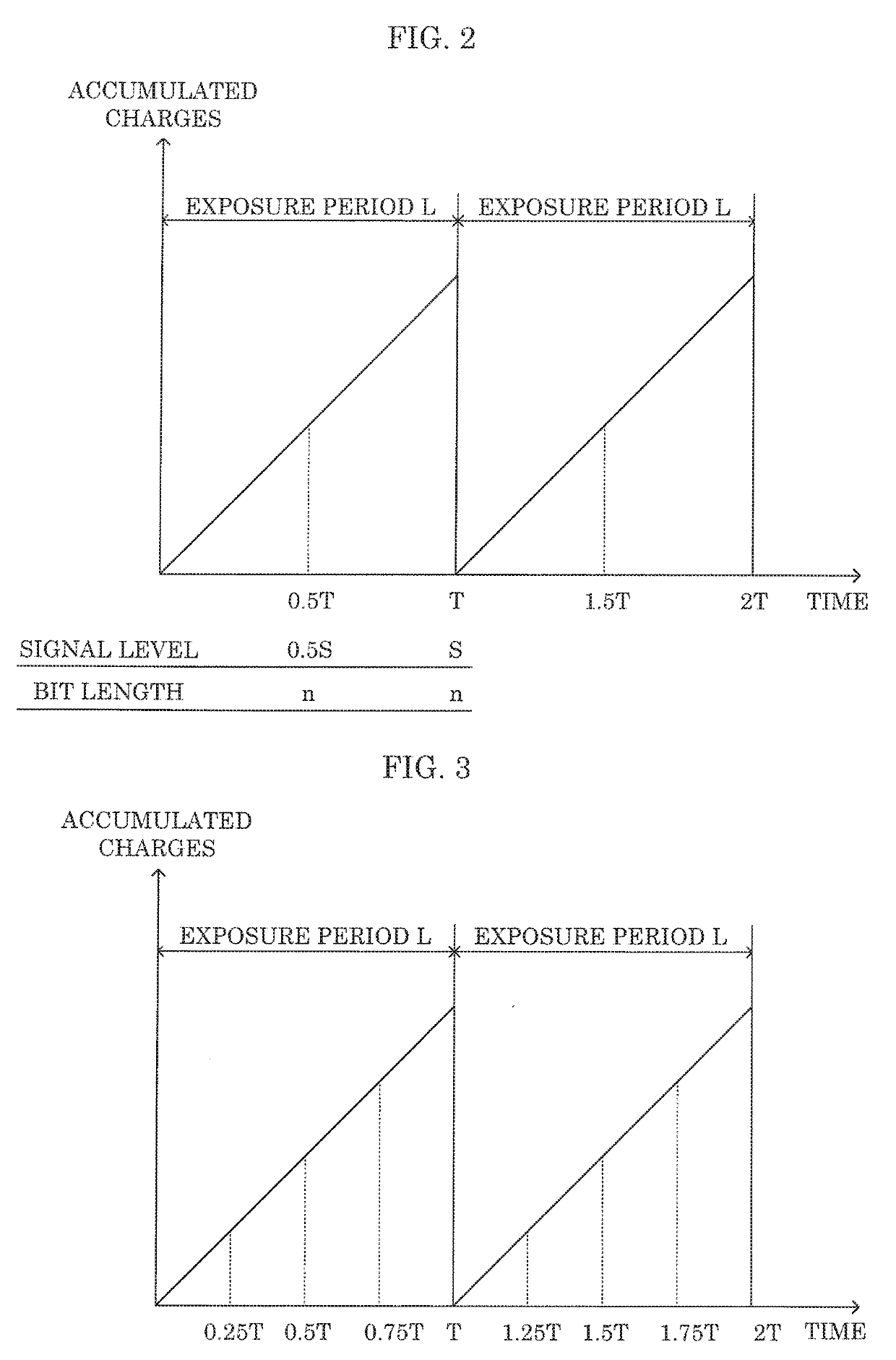
[0061]Embodiment 1 described above illustrates a case where image signals are read out twice within one exposure period L. However, the number of times of reading out image signals within one exposure period L may be three times or more. In any case, image processor 160 reads out image signals a plurality of times from imaging element 10 within one exposure period L, calculates a target gain value based on a target level calculated based on the signal level of the last read-out image signal in one exposure period L, and an added signal obtained by adding up the plurality of read-out image signals, and multiplies the added signal by the target gain value.

[0062]This Modified Example 1 illustrates a case where image signals are read out four times within one exposure period L.

[0063]FIG. 3 is an explanatory diagram illustrating a read-out timing of an image signal according to Modified Example 1. As illustrated in FIG. 3, image processor 160 reads out image signals four times from imagi...

modified example 2

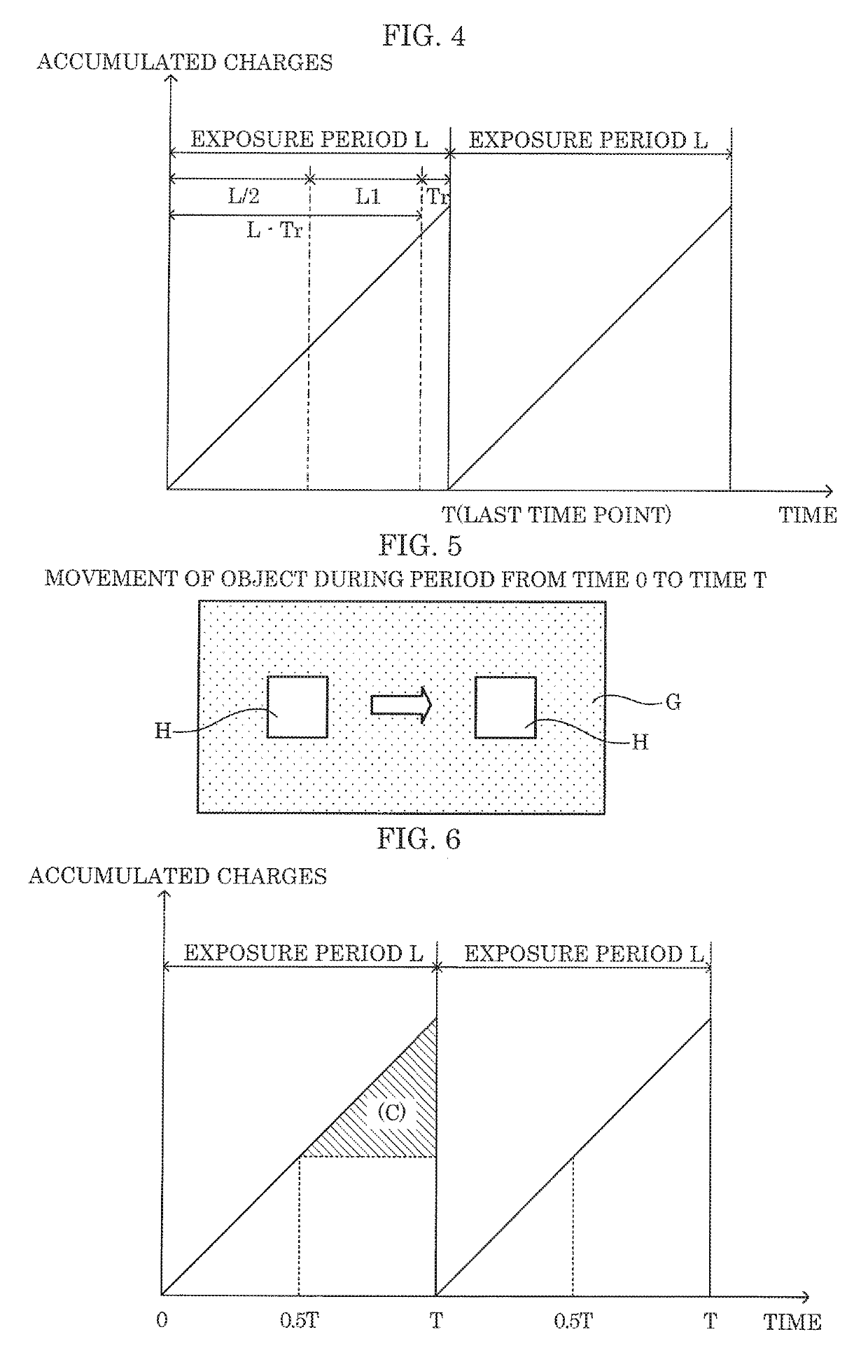
[0066]Embodiment 1 described above illustrates a case where one exposure period L is equally divided and image signals are read out at the divided points. However, if image signals are read out a plurality of times within one exposure period L, the read-out timing is not particularly limited. This Modified Example 2 illustrates a case where image signals are read out a plurality of times without equally dividing exposure period L.

[0067]FIG. 4 is an explanatory diagram illustrating a read-out timing of an image signal according to Modified Example 2.

[0068]As illustrated in FIG. 4, image processor 160 reads out image signals twice within one exposure period L. Specifically, image processor 160 sets the last read-out timing in the number of times of reading out image signals within one exposure period L as a last time point in the exposure period, and sets the read-out timing other than the last read-out timing to be within period L1 equal to or longer than L / 2 of the exposure period a...


PUM


Abstract

An imaging device includes: an imaging element that outputs an image signal in a nondestructive manner; an image processor that performs predetermined processing on the outputted image signal to generate image data; and a controller that controls the image processor. Under control of the controller, the image processor reads out image signals from the imaging element a plurality of times within one exposure period, calculates a target gain value based on a target level and an added signal, and multiples the added signal by the target gain value to generate the image data. The target level is calculated based on a signal level of a last read-out image signal in one exposure period. The added signal being obtained by adding up the image signals read out the plurality of times.

Description

CROSS REFERENCE TO RELATED APPLICATIONS[0001]This application is a U.S. continuation application of PCT International Patent Application Number PCT / JP2018 / 025956 filed on Jul. 10, 2018, claiming the benefit of priority of Japanese Patent Application Number 2017-136688 filed on Jul. 13, 2017, the entire contents of which are hereby incorporated by reference.BACKGROUND1. Technical Field[0002]The present disclosure relates to an imaging device and a camera which capture an image.2. Description of the Related Art[0003]An imaging device that captures an image by using an image sensor has heretofore been known (for example, see Japanese Unexamined Patent Application Publication No. 2008-042180).[0004]Japanese Unexamined Patent Application Publication No. 2002-280537 discloses, as a MOS image sensor capable of global shutter driving, a configuration for writing electric charges generated in a photodiode into a nonvolatile memory transistor, and also discloses an image sensor capable of rea...

Claims


Application Information

Patent Timeline
IPC IPC(8): H04N5/243H04N5/235H04N5/232
CPCH04N5/243H04N5/2354H04N5/23212H04N5/2353H04N23/687H04N23/76H04N23/73H04N25/53H04N23/74H04N25/60H04N23/67H04N25/75H04N25/76
Inventor HAMASAKI, TAKESHI
Owner PANASONIC INTELLECTUAL PROPERTY MANAGEMENT CO LTD
Why Eureka
Try Eureka