
System and Computer-Implemented Method for Modeling the Three-Dimensional Shape of An Object by Shading of a Two-Dimensional Image of the Object

Inactive Publication Date: 2007-05-10
MENTAL IMAGES
View PDF41 Cites 2 Cited by
  • Summary
  • Abstract
  • Description
  • Claims
  • Application Information

AI Technical Summary

Benefits of technology

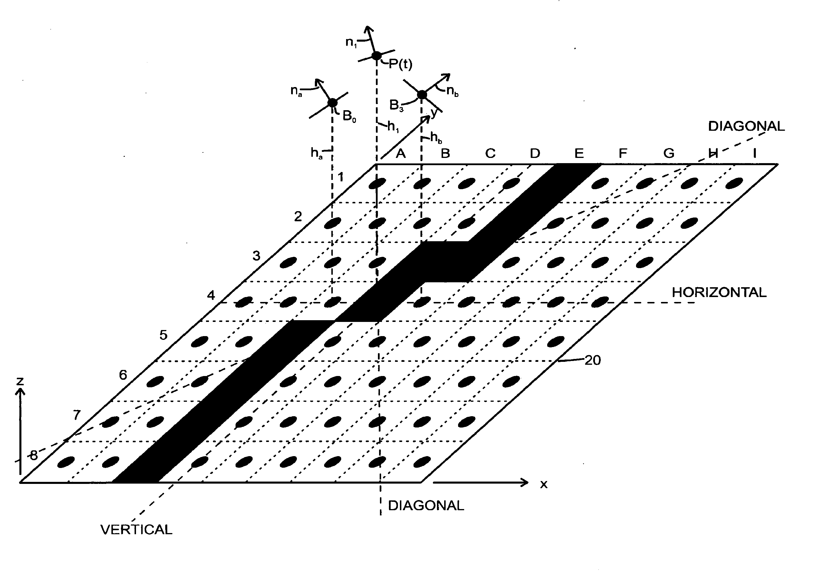
[0019] A computer graphics system constructed in accordance with the invention avoids the necessity of solving partial differential equations, which is required in prior art systems which operate in accordance with the shape-from-shading methodology.
[0020] Embodiments of the invention also allow the operator to perform conventional computer graphics operations in connection with the object, including rotation and spatial translation of the object to facilitate projection of an image of the object onto an image plane from any of a number of rotational orientations and spatial positions, and scaling or zooming to facilitate enlargement or reduction of the object and / or the image. In such embodiments, the operator can update the shading of the image from any particular three-dimensional rotational and / or translational orientation and position, and from the scaling or zoom setting, as selected by the operator. In addition, embodiments of the invention allow the operator to trim any surface fragment at any moment in time or the updated final object, which may consist of a plurality of such surface fragments, in a conventional manner by projecting two-dimensional trim curves onto the surface of the object. The operator can use the input device, operating in an appropriate drawing mode, to draw these trim curves on the image plane.

Problems solved by technology

Since images can be noisy and the assumptions noted above are sometimes not perfectly satisfied, there may be no solution using this methodology, and in any case there will be no unique solution.

Method used


Image

  • System and Computer-Implemented Method for Modeling the Three-Dimensional Shape of An Object by Shading of a Two-Dimensional Image of the Object
  • System and Computer-Implemented Method for Modeling the Three-Dimensional Shape of An Object by Shading of a Two-Dimensional Image of the Object
  • System and Computer-Implemented Method for Modeling the Three-Dimensional Shape of An Object by Shading of a Two-Dimensional Image of the Object

Examples


Embodiment Construction

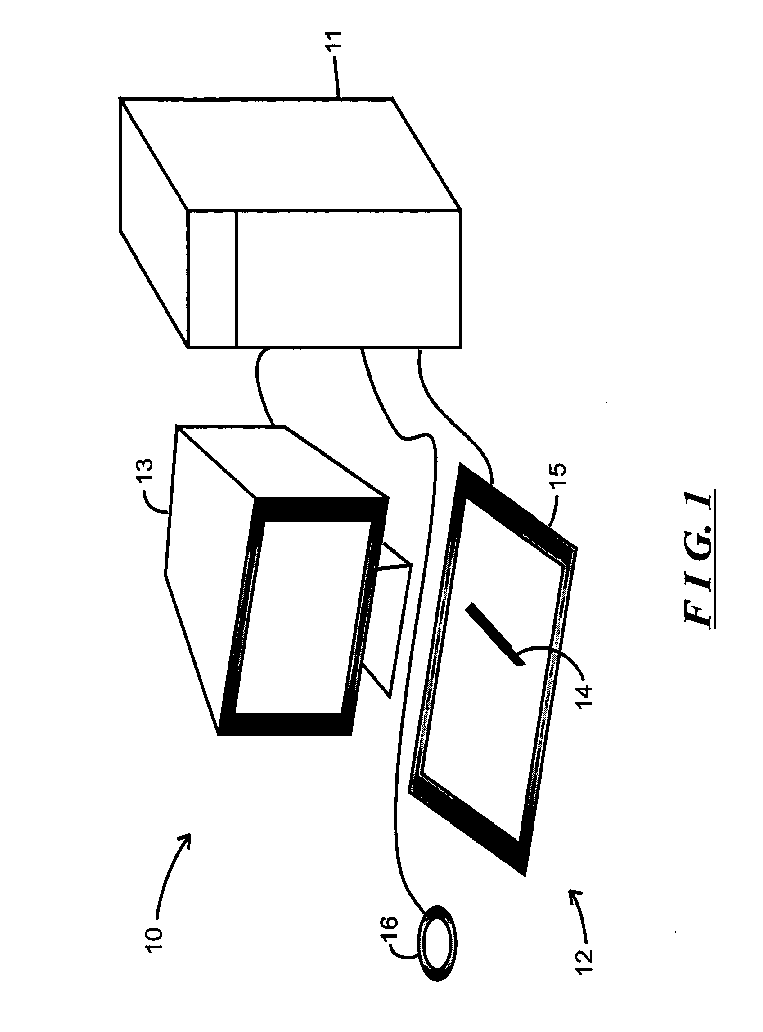
[0025]FIG. 1 depicts a computer graphics system 10 for generating a three-dimensional model of an object by shading as applied by an operator or the like to a two-dimensional image of the object in the given state of its creation at any point in time, constructed in accordance with the invention. With reference to FIG. 1, the computer graphics system includes a processor module 11, one or more operator input devices 12 and one or more display devices 13. The display device(s) 13 will typically comprise a frame buffer, video display terminal or the like, which will display information in textual and / or graphical form on a display screen to the operator. The operator input devices 12 for a computer graphics system 10 will typically include a pen 14 which is typically used in conjunction with a digitizing tablet 15, and a trackball or mouse device 16. Generally, the pen 14 and digitizing tablet will be used by the operator in several modes. In one mode, particularly useful in connectio...


PUM


Abstract

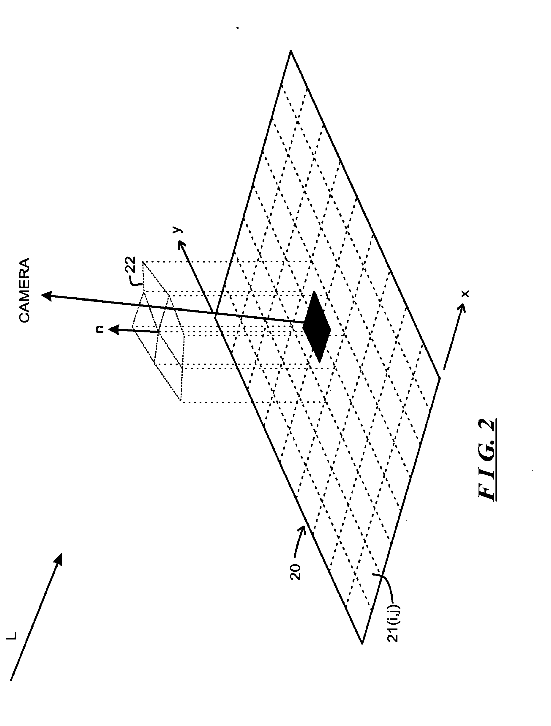
A computer graphics system generates a three-dimensional model of an object in an interactive manner under control of an operator. An initial model for the object to be modeled is displayed to the operator as illuminated from a particular illumination direction and projected onto an image plane. The operator can update shading of a pixel on the image plane, and, based on the updated shading, the computer graphics system generates an updated normal vector for the updated pixel, which identities the normal of the surface of the object projected onto the updated pixel. Using the updated normal vector field and a height field, which represents the height of the respective portion of the object as projected onto the respective pixels of the image plane, the computer graphics system generates an updated height value for the updated pixel, thereby to update the height field. The updated normal vector field and the updated height field define the updated model of the object, which corresponds to the updated shape of the object as updated based on the updated shading. The computer graphics system can then display to the operator an image of the object as defined by the updated model. If the updated model is satisfactory, the computer graphics system saves the updated model as the final model. On the other hand, if the updated model is not satisfactory, the operator can further update the shading and enable the computer graphics system to generate a further updated normal vector field and updated height field, thereby to generate a further updated model for the object. The operations can be repeated until the operator determines that the object is satisfactory.

Description

CROSS REFERENCE TO RELATED APPLICATIONS [0001] The present application for U.S. patent is a Continuation of U.S. patent application Ser. No. 10 / 795,704 filed Mar. 5, 2004 (Attorney Docket MENT-003D1), which is a divisional of 09.0027, 17.5 filed Feb. 20, 1998 (Attorney Docket MENT-003), now U.S. Pat. No. 6,727,383, which issued on Apr. 20, 2004, each of which is incorporated herein by reference. Also incorporated herein by reference is “The Shape-By-Shading Modeler,” a paper by Rolf Herken and Tom-Michael Thamm, attached hereto as an Appendix.FIELD OF THE INVENTION [0002] The invention relates generally to the field of computer graphics, computer-aided geometric design and the like, and more particularly to generating a three-dimensional model of an object. BACKGROUND OF THE INVENTION [0003] In computer graphics, computer-aided geometric design and the like, an artist, draftsman or the like (generally referred to herein as an “operator) attempts to generate a three-dimensional model...

Claims


Application Information

Patent Timeline
IPC IPC(8): G06T15/50G06T7/00
CPCG06T7/0053G06T15/80G06T2207/20092G06T7/507
Inventor HERKEN, ROLFTHAMM, TOM-MICHAEL
Owner MENTAL IMAGES
Learn More