
Method and apparatus for measuring acoustic mud velocity and acoustic caliper

a technology of acoustic mud velocity and acoustic caliper, which is applied in the direction of seismology for waterlogging, instruments, and reradiation, etc., can solve the problems of adversely affecting data integrity, borehole rugosity adversely affecting downhole data measurement,

Inactive Publication Date: 2003-09-09
BAKER HUGHES INC
View PDF8 Cites 57 Cited by
  • Summary
  • Abstract
  • Description
  • Claims
  • Application Information

AI Technical Summary

Benefits of technology

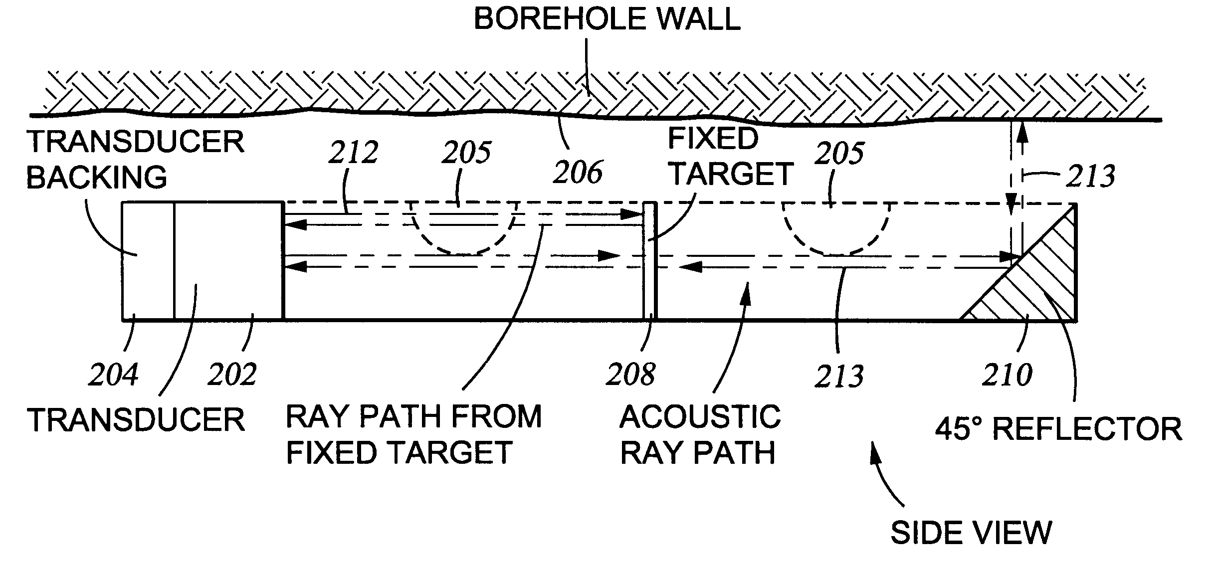
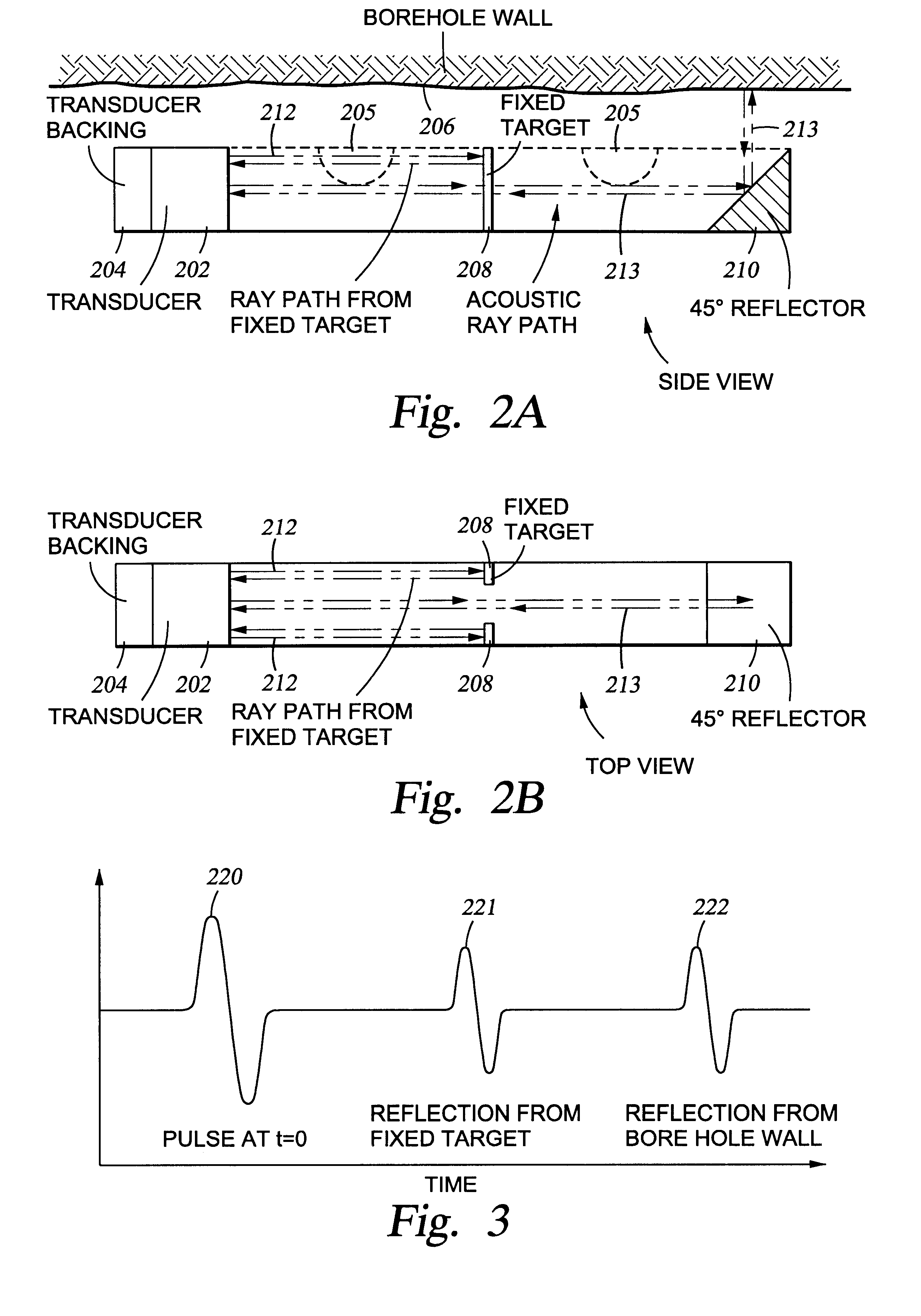
The present invention provides an acoustic standoff measurement wherein the two-way travel time is converted to distance. This conversion utilizes the precise measurement of mud velocity provided by the structure of the present invention. Mud velocity depends on the mud composition and pressure and temperature. The present invention provides a direct measurement of mud velocity and thus avoids the necessity of providing and using a second transducer for velocity measurements. In one embodiment of the present invention, the standoff transducer is recessed 0.5 to 1 inch inside the mandrel. Because the transducer is recessed, the minimum travel time will occur when the tool is flush against the borehole wall and the mud velocity can then be determined by dividing the minimum travel time by the distance the transducer is recessed. This enables conversion of the two-way travel-time data into standoff and to provide quality control and to correct NMR data for mud signal corruption. The present invention also measures signal amplitude and attenuation of the transmitted signal based on the amplitude of a return pulse from a fixed reflector and adjusts the transmitter pulse amplitude and / or receiver gain based on the amplitude from the fixed reflector to provide automatic gain control based on mud attenuation.

Problems solved by technology

Spatial irregularities in the borehole walls can adversely affect data integrity, unless these irregularities are detected and accounted for in data processing and / or acquisition.
Borehole rugosity adversely affects downhole data measurements which are designed to assess the potential for hydrocarbon bearing formations adjacent a borehole.
For example, cavities in the borehole wall can adversely affect measurements taken by downhole devices such as Nuclear Magnetic Resonance (NMR) devices.
Secondly, since the magnetic moments are non-aligned with the static field, they experience a perpendicular force which causes them to precess around the static field.
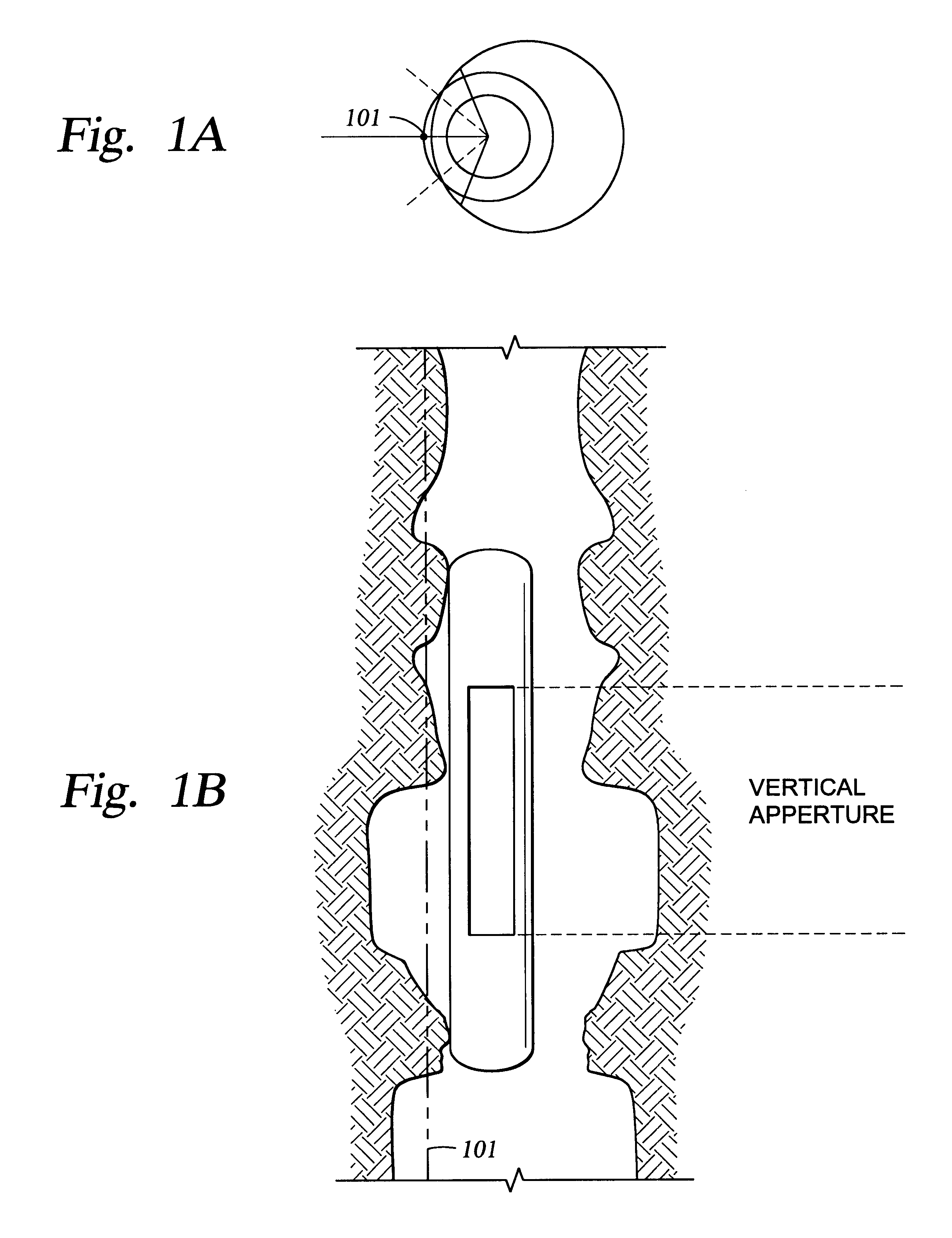
Since the sensitive region lies close to the surface of the borehole cavity, geometric anomalies in the surface of the wellbore can cause portions of the sensitive region to lie inside the borehole cavity rather than inside the rock formation, causing NMR signals to be received from what is contained inside the borehole, usually drilling mud.
Prior methods have used caliper arms to determine the distance from the tool body to the borehole wall, however, such methods are crude and do not yield precise measurements.
In yet a third possibility, there can be a significant amount of washout, where certain segments of the borehole wall have separated and fallen away, leaving a cavity to one side of the borehole.
Although corrections for invasive mud signals have been made in other logging methods, there is no similar method designed for use in NMR well logging.
Physical limitations make it difficult to build side looking NMR tool that traverses a borehole and reads deeply into an adjacent formation.
Thus, the NMR data collected with such tools can be corrupted by NMR signals originating from the borehole mud.
Gamma-Gamma density tools also are relatively shallow reading and their readings can also be adversely affected by even small-scale vertical rugosity, in which the skid is not capable of maintaining well bore contact.
No similar means of identifying questionable NMR data exists for data from the MRIL or CMR tools.
The mechanical standoff measurements are limited in accuracy, the amount of data points gathered and resolution.
However, it is difficult to precisely know the makeup of the mud in the borehole at every depth and hence critical factors (e.g. water, oil and gas concentration, cuttings load, etc.) may not be known well enough to predict the mud velocity at every depth.
Further, the addition of gas or suspended particles, cuttings, will also change the mud velocity.
This renders measurements of standoff and / or borehole caliper based on acoustic time of flight measurements imprecise.

Method used


Image

  • Method and apparatus for measuring acoustic mud velocity and acoustic caliper
  • Method and apparatus for measuring acoustic mud velocity and acoustic caliper
  • Method and apparatus for measuring acoustic mud velocity and acoustic caliper

Examples


Embodiment Construction

The present invention provides a means for measuring acoustic mud velocity and acoustic caliper. The present invention provides a device that enables simultaneous measurement of the acoustic mud velocity, and acoustic standoff or acoustic caliper. A precise mud velocity is measured with every firing of the transducer, thus a very precise standoff and / or caliper measurement is continuously provided by the present invention. The standoff and borehole caliper measurements and correction of other signals affected by the standoff and borehole caliper. The standoff and mud velocity measurements are used to correct other sensor data (e.g. gamma-gamma density, neutron, NMR) or for borehole geometry data. The borehole geometry data may be used for drilling efficiency (sloughing vs. spalling shale vs. washed out sands) or as input into geomechanical studies.

The method and apparatus of the present invention may be used with any one of several devices. The present invention is useful whenever a...


PUM


Abstract

A method and apparatus for determining acoustic mud velocity and bore hole caliper in a downhole environment. A highly accurate acoustic signal is adjusted for mud velocity as continuously measured. The borehole standoff is utilized to compensated data collected downhole in determining a parameter of interest in the wellbore or an adjacent formation.

Description

1. Field of the InventionThe invention relates generally to the field of downhole hydrocarbon recovery and formation analysis and in particular to a method and apparatus for measuring acoustic mud velocity and acoustic caliper in the downhole environment.2. Description of the Related ArtBorehole caliper is an important factor in the available accuracy and effectiveness of downhole data gathering instruments. Spatial irregularities in the borehole walls can adversely affect data integrity, unless these irregularities are detected and accounted for in data processing and / or acquisition. Borehole rugosity adversely affects downhole data measurements which are designed to assess the potential for hydrocarbon bearing formations adjacent a borehole. For example, cavities in the borehole wall can adversely affect measurements taken by downhole devices such as Nuclear Magnetic Resonance (NMR) devices. Thus, there is a need for an accurate downhole measurement of borehole rugosity.NMR device...

Claims


Application Information

Patent Timeline
IPC IPC(8): G01V1/46G01V1/40
CPCG01V1/46E21B47/085
Inventor GEORGI, DAN T.
Owner BAKER HUGHES INC
Learn More