
Exercise apparatus

a technology of exercise equipment and cable, which is applied in the direction of sport equipment, muscle exercise equipment, gymnastic exercise, etc., can solve the problems of inability to compensate for a change in the length of the cable, and it is difficult for a person to stand in the center region while using the apparatus

Inactive Publication Date: 2008-02-26
BVP HLDG
View PDF12 Cites 58 Cited by
  • Summary
  • Abstract
  • Description
  • Claims
  • Application Information

AI Technical Summary

Benefits of technology

"The present invention provides an exercise apparatus that allows the cable exit point to be changed from one position to another along a semi-circular arc without requiring a separate cable take-up mechanism to adjust the length of the cable. The apparatus includes an arcuate frame member, frame support, cable pulleys, a source of resistance, a handle, and a flexible cable. The apparatus allows a user to change the position of the cable exit point by moving the first cable pulley along the arc of the frame member. The distance between the two cable pulleys remains constant, regardless of the position of the first pulley. The apparatus may include one or two arcuate frame members, with fittings or a trolley for attachment of the cable pulleys. The technical effects of the invention include the ability to change the cable exit point without adjusting the length of the cable and the freedom of movement for the user in various training positions."

Problems solved by technology

While this arrangement allows the positions of the trolley tracks to be moved laterally (horizontally) about the hinged connection points, thus providing additional flexibility to the user, this apparatus has no cable take-up mechanism and therefore cannot compensate for a change the length of the cable when the position one of the trolleys along its track is changed.
Also, because the two semi-circular trolley tracks are hinged together, top and bottom, it is difficult for a person to stand in the center region while using the apparatus.

Method used


Image

  • Exercise apparatus
  • Exercise apparatus
  • Exercise apparatus

Examples


third embodiment

[0046]FIGS. 10 and 11 show a third embodiment in which the frame members 26a and 26b are hinged, top and bottom, for movement about a respective vertical axis and wherein the pulleys 18a and 18b are supported by a slide which runs in a slot. In this case, the cables 12a and 12b are passed around a single central pulley 22a, 22b, respectively, which is mounted for rotation and gimbaled about a vertical axis (FIG. 10). The cable is then brought vertically to upper pulleys 24a, 24b and outward to pulleys 80a and 80b before descending downward to the respective resistance source (weight stack) 16a and 16b.

fifth embodiment

[0047]FIG. 12 illustrates a fifth embodiment, similar to the embodiment of FIGS. 10 and 11, wherein the pulleys 20a and 20b are removably attached to one of a plurality of fittings 90a and 90b on the frame members 26a, 26b, respectively.


PUM


Abstract

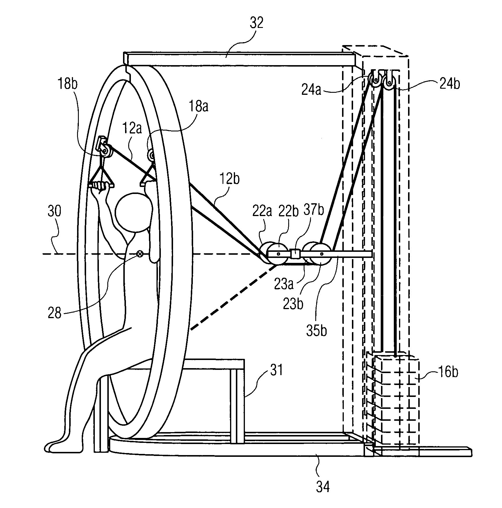
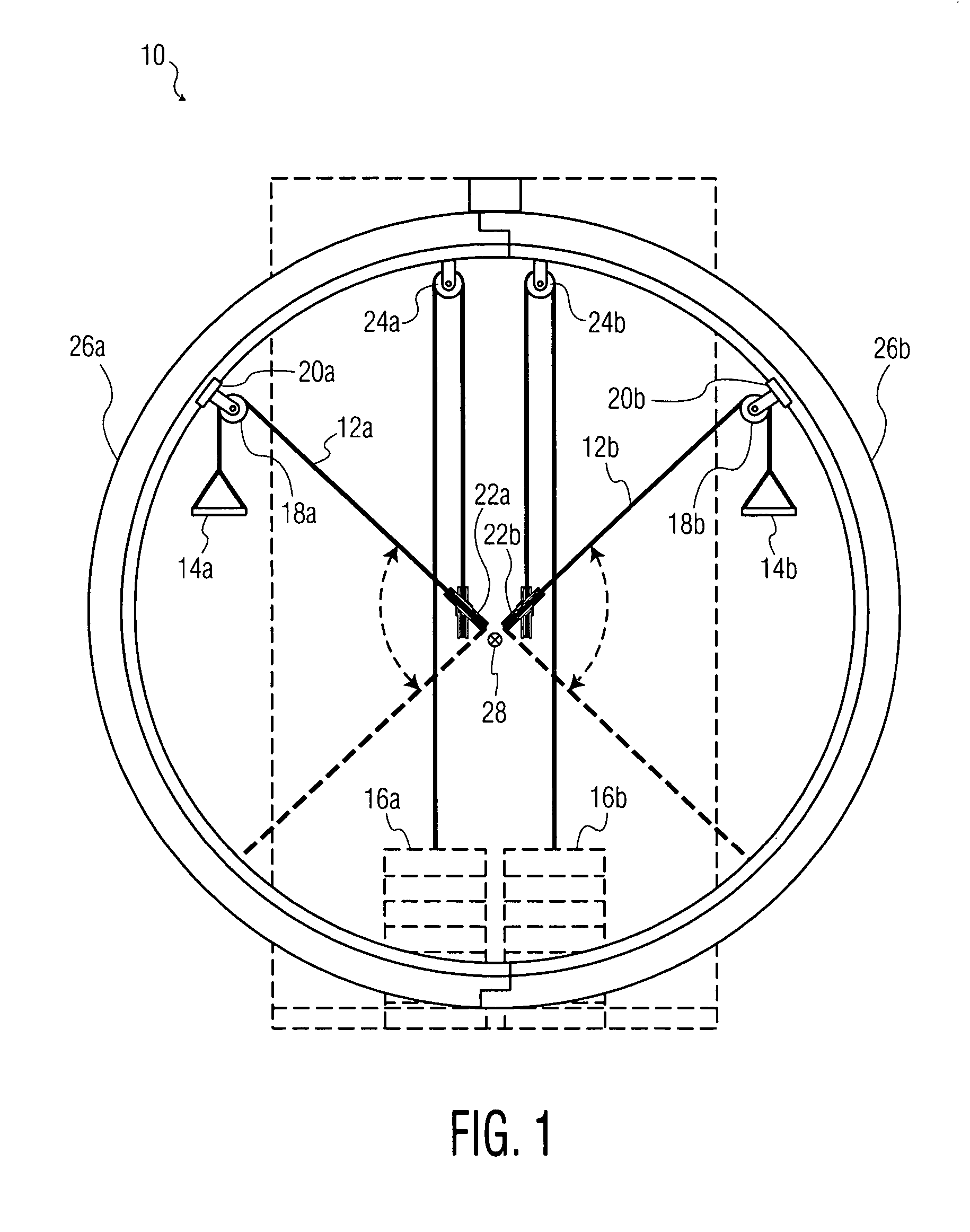
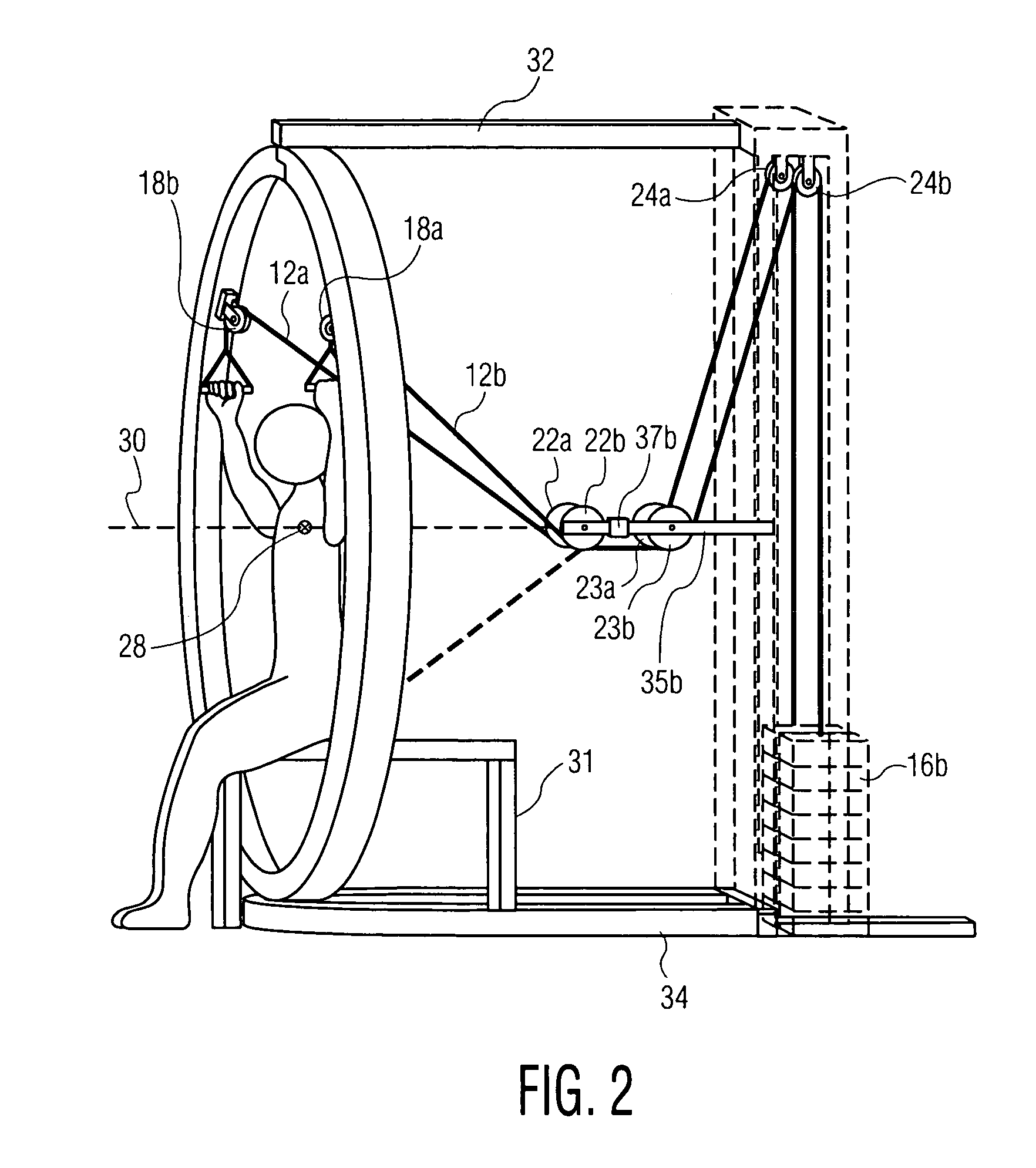
Exercise apparatus is disclosed which enables a user to pull a cable against a source of resistance from a pulley arranged at one of a number of points around a substantially circular arc. The exercise apparatus includes: an arcuate frame member forming a segment of an approximate circle having a center, the circle with its center lying in an imaginary plane; (b) a frame support for supporting the frame member in a upright position such that the plane is substantially vertically oriented; (c) a first cable pulley adapted to be attached to the frame member at one of a plurality of positions along the arc; (d) a second cable pulley fixedly mounted in the vicinity of a substantially horizontal, imaginary first axis that extends perpendicular to the plane and passes through the center of the circle; (e) at least one source of resistance; (f) a handle adapted to be grasped by a user; and (g) a flexible cable having a proximate end attached to said handle and a distal end coupled to said at least one resistance source, the cable passing through both the first pulley and the second pulley.

Description

CROSS-REFERENCE OF RELATED APPLICATION[0001]This application claims priority from Provisional Patent Application No. 60 / 673,524 filed Apr. 21, 2005, and entitled “EXERCISE APPARATUS”.BACKGROUND OF THE INVENTION[0002]The present invention relates to exercise apparatus of the type which allows a user to repeatedly pull on a handle which is attached to a cable. A source of resistance, such as one or more weights, springs, elastic bands, and / or hydraulic or pneumatic dampers, is coupled to a distal end of the cable to counteract the tension applied to the cable by the user.[0003]Exercise apparatus of this type is well known. It is also known to design such exercise apparatus so that the cable portion leading to the handle emanates from a cable pulley at a selected exit point along a circular arc formed by an arcuate frame member of the machine. This exit point may be determined by the position of a trolley that supports the cable pulley. This trolley can be moved along an arcuate track ...

Claims


Application Information

Patent Timeline
Patent Type & Authority Patents(United States)
IPC IPC(8): A63B21/062A63B21/00
CPCA63B21/055A63B21/062A63B21/154A63B21/156A63B23/12A63B21/00061A63B21/00065A63B21/0083A63B21/0087A63B21/0428A63B21/0552A63B2208/0204A63B2208/0233A63B23/03541A63B23/1209A63B21/0628A63B21/4035A63B21/4043
Inventor PIANE, JR., ROBERT A.
Owner BVP HLDG
Learn More