
Insulator-coated soft magnetic powder, method for producing insulator-coated soft magnetic powder, powder magnetic core, magnetic element, electronic device, and vehicle

a technology of insulator coating and soft magnetic powder, which is applied in the direction of magnetic bodies, cores/yokes, magnetic elements, etc., can solve the problems of joule loss (eddy current loss) due, significant increase of current, and deterioration of the moldability of soft magnetic metal particle powder

Active Publication Date: 2019-08-29
SEIKO EPSON CORP
View PDF0 Cites 6 Cited by
  • Summary
  • Abstract
  • Description
  • Claims
  • Application Information

AI Technical Summary

Benefits of technology

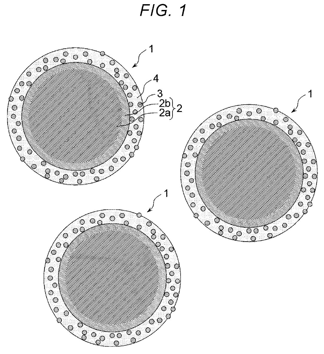
The invention is a way to create a special type of magnetic powder that is insulated from other materials. This is useful for making certain types of products that require the magnetic powder to be insulated from other materials. The magnetic powder has a soft magnetic core with a layer of oxide on top, and a layer of ceramic particles on top of that with insulation properties. The ceramic particles are made up of phosphorus oxide, bismuth oxide, zinc oxide, boron oxide, tellurium oxide, and silicon oxide. The proportions of these components are important, and are described in the patent text. The technical benefit is that this special magnetic powder can be made to have insulation properties, which is useful for making certain products that require insulated magnetic powder.

Problems solved by technology

However, in the case where the driving frequency of such a magnetic element is increased, there arises a problem that a Joule loss (eddy current loss) due to an eddy current is significantly increased in a magnetic core included in each magnetic element.
When such aggregation occurs, characteristics as a powder are degraded, and therefore, the moldability of the soft magnetic metal particle powder is deteriorated.
Therefore, when compaction molding is performed, sufficient filling performance cannot be obtained, and the magnetic characteristics of the resulting powder magnetic core are deteriorated.

Method used


Image

  • Insulator-coated soft magnetic powder, method for producing insulator-coated soft magnetic powder, powder magnetic core, magnetic element, electronic device, and vehicle
  • Insulator-coated soft magnetic powder, method for producing insulator-coated soft magnetic powder, powder magnetic core, magnetic element, electronic device, and vehicle
  • Insulator-coated soft magnetic powder, method for producing insulator-coated soft magnetic powder, powder magnetic core, magnetic element, electronic device, and vehicle

Examples


first embodiment

[0144]First, a choke coil to which a magnetic element according to a first embodiment is applied will be described.

[0145]FIG. 6 is a schematic view (plan view) showing the choke coil to which the magnetic element according to the first embodiment is applied.

[0146]A choke coil 10 shown in FIG. 6 includes a powder magnetic core 11 having a ring shape (toroidal shape) and a conductive wire 12 wound around the powder magnetic core 11. Such a choke coil 10 is generally referred to as “toroidal coil”.

[0147]The powder magnetic core 11 is obtained by mixing the insulator-coated soft magnetic powder including the insulator-coated soft magnetic particles 1 described above, a binding material (binder), and an organic solvent, supplying the obtained mixture in a molding die, and press molding the mixture. That is, the powder magnetic core 11 includes the insulator-coated soft magnetic powder according to this embodiment. Such a powder magnetic core 11 has a favorable insulating property between...

second embodiment

[0165]Next, a choke coil to which a magnetic element according to a second embodiment is applied will be described.

[0166]FIG. 7 is a schematic view (transparent perspective view) showing the choke coil to which the magnetic element according to the second embodiment is applied.

[0167]Hereinafter, the choke coil to which the second embodiment is applied will be described, however, in the following description, different points from the choke coil to which the first embodiment is applied will be mainly described and the description of the same matter will be omitted.

[0168]A choke coil 20 shown in FIG. 7 is obtained by embedding a conductive wire 22 molded into a coil shape inside a powder magnetic core 21. That is, the choke coil 20 is obtained by molding the conductive wire 22 with the powder magnetic core 21.

[0169]According to the choke coil 20 having such a configuration, a relatively small choke coil is easily obtained. In the case where such a small choke coil 20 is produced, by u...

example 1

[0193]First, a metal powder (core particles) of an Fe—Cr—Al-based alloy produced by a water atomization method was prepared. This metal powder is an Fe-based alloy soft magnetic powder containing Cr and Al. The average particle diameter of the metal powder was 10 μm.

[0194]At the same time, a ceramic powder (ceramic particles) of boron nitride (BN) was prepared. The average particle diameter of this powder was 50 nm.

[0195]Further, a P2O5-based glass powder (glass material) was prepared. The average particle diameter of this powder was 3.0 μm.

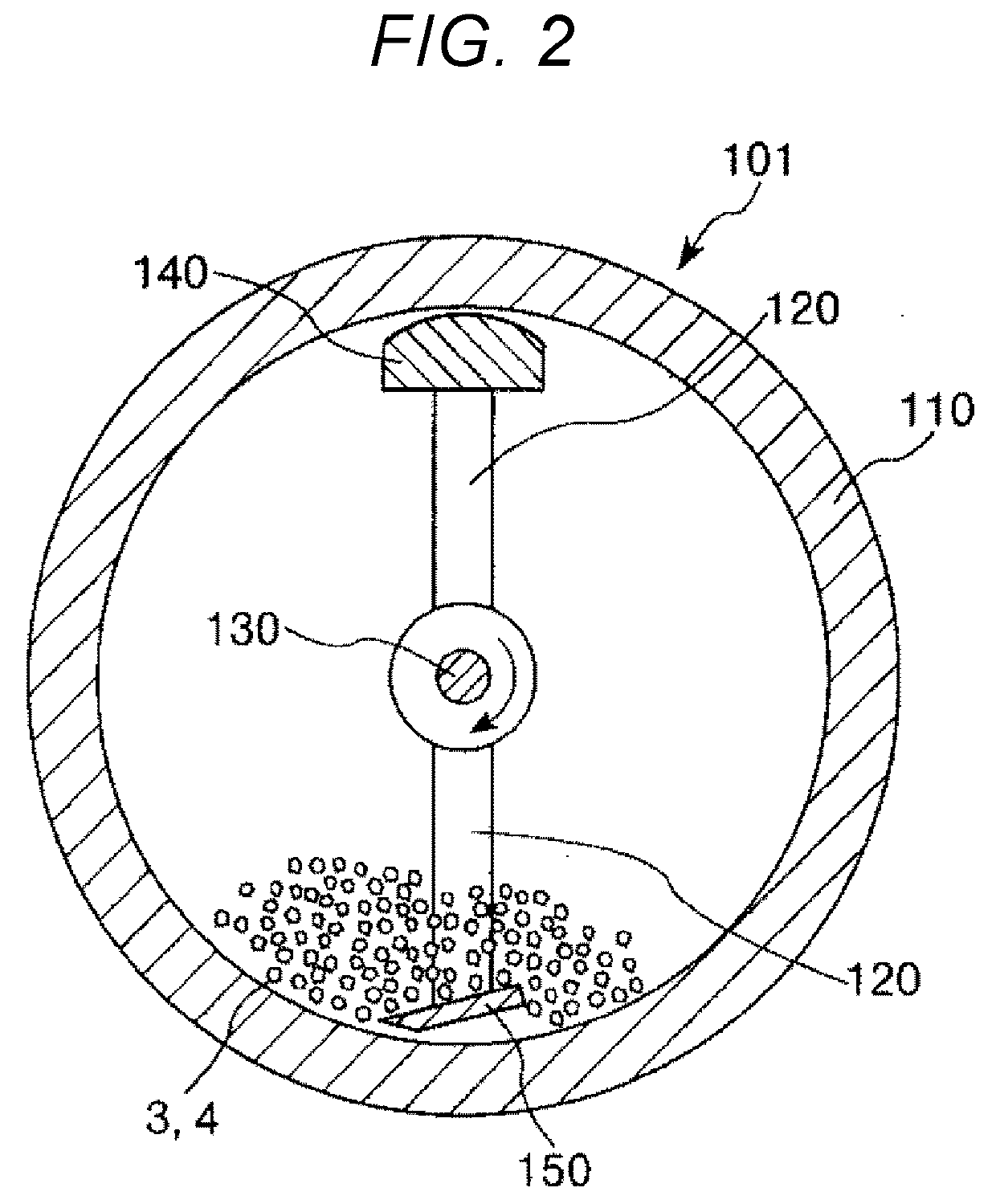
[0196]Subsequently, the metal powder, the ceramic powder, and the glass powder were fed into a friction mixer, and mechanical compression and friction actions were caused. By doing this, the ceramic powder was adhered to the surfaces of the metal particles.

[0197]Subsequently, the metal powder having the ceramic powder adhered thereto was subjected to a heat treatment, whereby an insulator-coated soft magnetic powder was obtained. The heat treatme...


PUM

PropertyMeasurementUnit
Thicknessaaaaaaaaaa
Thicknessaaaaaaaaaa
Soft magnetismaaaaaaaaaa

Abstract

An insulator-coated soft magnetic powder includes core particles each of which includes a base portion containing a soft magnetic material and an oxide film provided on the surface of the base portion and containing an oxide of an element contained in the soft magnetic material, ceramic particles which are provided on the surface of each of the core particles and have an insulating property, and a glass material which is provided on the surface of each of the core particles, has an insulating property, and contains at least one type of phosphorus oxide, bismuth oxide, zinc oxide, boron oxide, tellurium oxide, and silicon oxide as a main component, wherein the ceramic particles are included in a proportion of 100 vol % or more and 500 vol % or less of the glass material.

Description

BACKGROUND1. Technical Field[0001]The present invention relates to an insulator-coated soft magnetic powder, a method for producing an insulator-coated soft magnetic powder, a powder magnetic core, a magnetic element, an electronic device, and a vehicle.2. Related Art[0002]Recently, reduction in size and weight of a mobile device such as a notebook personal computer has advanced. However, in order to achieve both reduction in size and enhancement of performance at the same time, it is necessary to increase the frequency of a switched-mode power supply. At present, the driving frequency of a switched-mode power supply has been increased to several hundred kilo hertz or more. However, accompanying this, a magnetic element such as a choke coil or an inductor built in a mobile device also needs to be adapted to cope with the increase in the frequency.[0003]However, in the case where the driving frequency of such a magnetic element is increased, there arises a problem that a Joule loss (...

Claims


Application Information

Patent Timeline
IPC IPC(8): H01F1/24H01F1/33H01F1/147B22F1/02B22F1/16
CPCH01F1/24H01F1/33H01F1/147B22F2303/01B22F2301/35B22F2302/20B22F2302/25B22F1/02H01F41/0246B22F1/16H01F3/08B22F2009/0828B22F2998/10
Inventor NAKAMURA, ATSUSHI
Owner SEIKO EPSON CORP
Learn More